HI-FI AM transmitter
HI-FI AM transmitter

Fellow Radiophiles,
I have distilled some of what I have learned in this forum into a new HI-FI AM transmitter design. This design takes lessons from earlier AM transmitter designs and from what I learned about neutralization.
One thread that was particularly instructive for me dealt with the AM modulator in the Granco ARC60 FM-to-AM converter for car use. I learned here about problems with spurious FM modulation, and distortion in the modulation process.
For completeness sake, I repeat here a list of AM transmitter threads that I am aware of:
1 Watt AM Transmitter (solid state)
Home made AM transmitter with dual gate mosfet
A survey of AM modulator/transmitters
Another survey of AM modulators/transmitters
Am tube modulator this is one of the most extensive AM transmitter threads in German (I read it with the Google translator).
Granco-ARC60 AM Modulator/transmitter runs off 12.6VDC.
High Performance modulator with Resistance stabilized oscillator
Another relevant thread explains neutralization of grid to plate capacitance (Miller capacitance) in the analysis of the Grundig 5040W/3D. The topic of neutralization came up at different points in the 5 part analysis with particulary enlightening explanations and analysis by Hans Knoll. One particularly thourough analysis of neutralization in IF amplifiers was contributed to the Grundig 5040W/3D thread by Andreas Steinmetz.(I read this thread with the Google translator)
The operation of Dual Control Pentodes is also directly relevant to this design.
Single Pentode Transmitter concept
Circuit blocks
 1- Cathode follower oscillator with undistorted sine waves at the tank voltage and at the cathode current.
 2- Suppressor grid G3 modulation with complementary modulation push-pull outputs at the plate and screen grid. The RF phase at the grid and plate match, but the relative amplitude between plate and screen is controlled by the suppressor grid G3. The 6AS6 dual control pentode was chosen because it was designed for easy control of the plate and screen currents by the suppressor grid voltage G3. Other pentodes can be made to work but with different operating voltages at the plate and screen grid G2. Doug Coulter suggested the 6AS6, and it became the ideal choice for single supply operation.
While suppressor grid G3 controls the RF amplitude at the plate and screen, it has negligible effect on the amplitude of the oscillation at the control grid G1 and cathode.
The most important aspect of this modulation approach is that G3 operates in the middle of it's linear range to effect a low distortion two-quadrant multiplication of constant AC cathode current because the output is taken as the difference between plate and screen currents. A zero carrier output occurs when the suppressor grid G3 voltage apportions the plate and screen currents to drive the output transformer with equal amplitude. The AC RF phase of the plate and screen currents is always equal and the same as the cathode current. When the transformer is driven equally by the plate and screen, the net RF output at the transformer secondary is zero. This is how the carrier can be completely suppressed without distortion.
The carrier suppression bias level at suppressor grid G3 will vary from tube to tube and this level is adjustable with an external control to cover this variation. G3 bias is best set more positive than the null point, where the G3 transfer function is most linear. A variation of this bias changes the carrier amplitude, and thus the modulation percentage, for a fixed audio input. The 2Vp-p output from a CD player is enough to get 100% modulation. If the null point is at -6V for a particular tube, G3 is then biased at -5V for 100% modulation. But the output RF voltage could be doubled if the G3 bias were moved to -4V and the modulation input increased to 4Vp-p.
Modern AM radios cope well with high modulation nearing 100%, but pre-war sets were designed for lower modulation levels. 50% modulation sounds nice on my regenerative grid-leak detectors.
(Perhaps having a fixed opposing RF added to a high powered plate modulated class C transmitter was how old tube transmitters could achieve 100% Plate modulation without cutoff distortion. Any historic info on this would be appreciated.)
One way to envisage the two quadrant multiplication of G3xG1, which is output in complementary fashion at screen grid G2 and the Plate, is to think of G3 as one input to a differential pair, with the complementary outputs at screen grid G2 and the Plate. The tail current is provided by the cathode under the control of control grid G1. The sum of plate and screen currents is very independent from the voltage at G3; the sum of the plate and screen currents depends on the control grid G1, which is the other input to this two quadrant multiplier. The Audio modulation signal appears as a differential component at the plate and screen, while the RF oscillation at the cathode appears as a common mode component. The net modulated signal is the differential component of the product of these two signals.
 3- Frequency Stability.
There are at least three distinct problems facing frequency stability. One is sensitivity to output loading. Another problem is the real time sensitivity of frequency to the modulating audio signal. This is spurious FM modulation. Yet, another problem is overall frequency stability as a function of tube aging, supply voltage and temperature.
Insensitivity to output loading was achieved with the high fixed 1500pF capacitance presented to the control grid with the 1/3x scaling to the top of the tank circuit. Another measure of insensitivity is given by relegating the oscillator function to the grid and cathode. The plate and screen are not directly involved in the oscillator operation.
Frequency insensitivity to audio modulating signals can be achieved with careful Neutralization, or balancing of Miller capacitance from G2 to G1 and from P to G1 seeks to keep total Miller capacitance feedback gain independent of modulation to minimize or eliminate FM modulation. This is a key problem with single tube transmitters, as Jacob Roschy found from direct experience; see Granco AM modulator.
This trim is presented here only as a suggestion, because the transformer turns ratio yielded a negligible 100Hz of spurious FM modulation. When I tried this neutralization adjustment with 1pF from the plate to the control grid, the spurious FM modulation dropped to 30Hz for a sweep of G3 from 0V to -10V. The un-neutralized insensitivity was somewhat fortuitous because it depends on the layout of the components. I have no Neutralization trim in my final construction because it was not needed. Note that the 10k trim pot replaces the 10k output load. It makes sense that the needed neutralization capacitance would be from plate to G1 because the parasitic from G2 to G1 is necessarily larger than the parasitic capacitance from the plate to G1.
The 10K output load bounds the output amplitude to about 1Vp-p if the suppressor grid G3 is biased between 0V and the suppressed carrier bias level. This relatively modest output swing helps to keep the frequency insensitive to antenna loading and audio modulation.
The last frequency stability problem is long term insensitivity to temperature, tube gain and supply voltage. The large fixed capacitance presented to the grid also helps here, but the key aspect of the design that insures insensitivity to these environmental parameters is the AGC regulation of the class A oscillator loop gain of 1. This high gain AGC loop forces the cathode resistance to 600Ω as described above. This means that the tube may loose gain over time, or the supply voltage may vary, or the tube may warm up slowly over time, but it's gain remains fixed by the AGC loop. These environmental inputs simply result in a variation of the AGC bias level and total RF output. Keeping the tube running at a fixed gain eliminates Miller gain variations because the Miller gain is now fixed by the AGC loop.
The gain of the AGC loop in this oscillator is a direct function of the linearity of the AC gain. In other words, with an ideal linear AC loop gain, the AGC gain loop gain is infinite. This is a direct result of the requirement for stable oscillation amplitude the loop gain of linear system be exactly one. Even a small amount of non-linearity greatly reduces this AGC loop gain because now it is possible for parts of the wave to operate at a loop gain higher than 1, while the rest of the wave operates at a gain that is lower than one. This real time variation of gain, which is a way of describing the cause of distortion, changes the frequency. Under these conditions a variation in temperature, supply voltage, or tube gain also results in a variation in frequency, in addition to the variation in amplitude. (This problem was at one time found by Dr. Bernard (Barney) Oliver of HP in the original founding product at HP, the Wien bridge sine wave RC oscillator. It was found that when the oscillators were too linear, with a distortion well below 0.01%, the light bulb stabilization AGC loop would become unstable from excessive loop gain. Bringing the distortion up to 0.01% was enough for AGC loop stability. I first learned of this in a riveting presentation by analog guru and staff scientist at Linear Technology, Jim Williams. Oliver published a formal paper on the subject)
One merit of the High Performance modulator with Resistance stabilized oscillator posted by Prof. Dietmar Rudolph is that the real time variation of the AC loop gain is kept low with the careful selection of a gain setting resistor. The real time stabilization of the oscillation amplitude of this loop still relies on a necessary level of distortion because there is no other way to change loop gain with a bias level. A conventional Class C oscillator also gets all of it's amplitude regulation from very wild real time variations of AC loop gain, but the use of a high Q tuned circuit, with less than a 1% loss per cycle (Q=100) can still achieve adequate stability despite the wild changes in real time gain because most of the time, the tube is cut off in class C and the period is defined by L and C.
The constructed transmitter
![]()
The power supply is based on a dual primary 120VAC mains transformer with two 6.3VAC secondaries (Signal Transformer DPC-12-2000). The original purpose of the dual primary configuration was for operation of the 6.3VAC secondaries from a 120VAC or 240VAC mains power. My local power is 120VAC, thus leaving a spare winding for the high voltage. The total available power using only one of the 120VAC windings as the primary, instead of both windings in parallel, reduces the maximum deliverable power because of higher Ohmic losses, but the total power required of this circuit is much less than what the transformer was designed to deliver. So much so, that I had to include a 5.1Ω resistor to drop the lightly loaded secondary to deliver 6.3VAC at 150mA to the 6AS6. R8,R9,C19,C10 eliminated hum injection and cathode RF leakage. I used the spare 6.3VAC winding to generate the variable 0 to -10V suppressor grid G3 bias, but the heater winding might have been used instead. I always include an appropriately sized fuse in all my constructions. This 64mA fuse is just slightly higher than the 50mA draw of the transmitter.
![]()
The transmitter was constructed in a Campbell's Tomato Soup can with built-in power supply. The paper label is an original 2010 edition, and not a fine art reproduction from 1968.
![]()
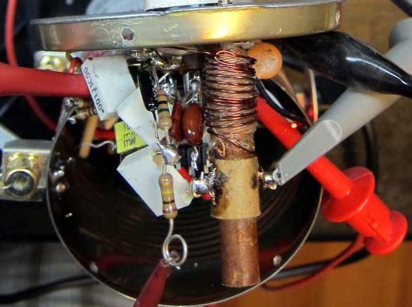
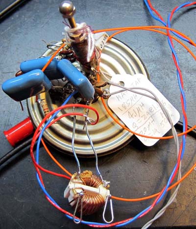 During development, I used a toroidal 1:1 transformer that is normally found as the mains filter in a PC power power supply. You could use one of these too if you add an extra winding for the output and double the number of turns for the plate side of the two existing windings.
Measured results
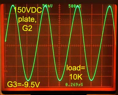
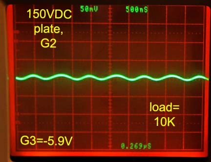
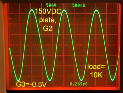
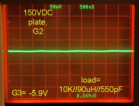
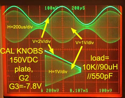
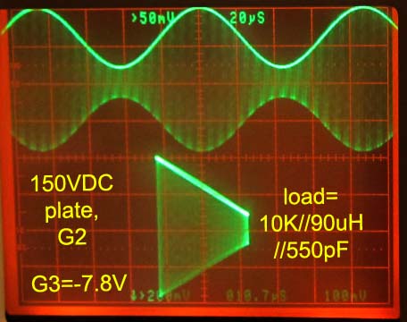
Note that when the suppressor grid G3 modulation input is biased to get zero RF carrier at the balanced null point, there is some residual second harmonic that is at least 20dB down from the full carrier. Loading the 10k secondary impedance with a tuned 89uH transmission loop reduces this second harmonic to the point of undetectability as seen in the photo on the left.
Parametric sweeps

Pentode to pentode variations
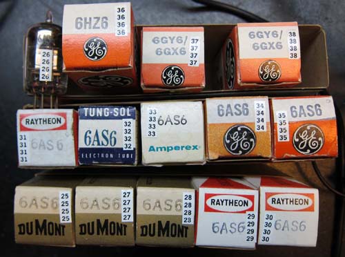
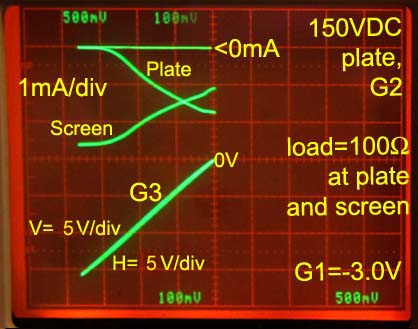
The following plots summarize operational results for 14 dual control pentodes of different brands and types, 11 of which were the 6SA6, one was the 6HZ6 and two were the 6GY6/6GX6. The pentodes are serialized from #25 to #38.
I conducted this evaluation of design robustness because of the well founded concern from Felix Schaffhauser over parametric variations among tubes.
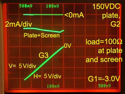
This survey resulted in the adjustment of the turns ratio of the push-pull output transformer load for Plate and Screen from 1:1 center tap to 2:1. The reason for this shift is that it was not possible to balance the plate and screen outputs of all tubes with a centered tap, but it was with a 2:1 turns ratio favoring the plate.
This reduced screen swing by 4, and increase plate swing by 4. This had a very fortuitous effect on Miller capacitance, and spurious FM modulation was reduced from 1kHz to 250Hz as G3 varies from 0V to plate cutoff.
If I increased the supply voltage to the plate, while operating with a 1:1 center tapped transformer primary, I would have increased the plate output, as an alternative to using the 2:1 primary tap favoring the plate. But separate supplies and windings for plate and screen are inconvenient.
Final thoughts, going further and acknowledgments.
Adjusting G3 with the knob is easily done by ear, by first listening for the RF null point on the knob with the characteristic "Donald Duck" sound, then easing back the bias to 50% of that setting. If more modulation is desired, the bias can be moved closer to the carrier null point just before clipping can be heard. G3 works as a control for the null carrier output and as a modulation control. The further from the null point, the lower the modulation percentage for a given audio input.
The output can drive a loop for reception on radios with loop antennas, or the 3-foot metal rod for radios with wire antennas that are sensitive to the electric field. The 3 foot rod and loop antenna work well together because the loop antenna tunes out some of the output parasitic capacitance.
The final listening tests sound absolutely sweet. It has made me want to check the alignment of a couple of my AM radios that show very little treble response. Perhaps I will cheat and add some over-coupling capacitance from primary to secondary of the last IF transformer to peak the treble response, while moving the AGC detector to the primary side to retain monotonic AGC response to the carrier.
I learned a lot from experimentation with Professor Pentode, however, much of what I know about neutralization and spurious FM modulation in AM transmitters was learned in the RMORG Forum.
This transmitter is dedicated to all of you.
Comments are welcomed, in particular, about any results from similar circuits or your built version of this circuit. It would be great to hear about a high power (1W) version of this transmitter with one of the GE Compactrons.
Best regards,
-Joe
To thank the Author because you find the post helpful or well done.
Excellent article

A big "thanks" to Joe Sousa for this excellent article about this HI-FI AM transmitter. After a lot of investigations, calculations and practical constructions Joe has come up with a very good concept of such an AM modulator. It is good to see, that with just one multigrid tube (here a Pentode, although a little bit special) a practical "Heimsenderlein" can be realized. I am sure, many of us will be happy to use his thoughts and recommendations for constructing a similar piece of hardware and appreciate the many considerations given in order to come up with own solutions.
I personally think, that there are so many nice tubes around that it will make sense to apply Joe's ideas to them and experiment with it and hopefully share the results with the community.
I hope that we can enjoy many such articles of Joe in our forum in the future.
Felix Schaffhauser
To thank the Author because you find the post helpful or well done.
Terrific!

Wow! This is a really intersting and thorough article. You da man, Joe!
To thank the Author because you find the post helpful or well done.