schaub: Schaub-Lorenz ; Goldy II P
schaub: Schaub-Lorenz ; Goldy II P

I've one Goldy II P (type 3620).
It's similar to 3133, so its schematic had been very useful to fix it.
The output transformer was repaired and some caps had been changed.
Now it is working.
BUT......:
It sounds loud (normal) in LW,MW, KW, but very low in UKW.
- A better aerial doesn't improve this a bit.
- ECC85 is not the problem (It was already checked).
- Also I can´t understand why its "Magic eye" tube shows better input signals in UKW than in MW, LW,KW. It might be the opposite....Don't you agree?
Do You know this models?
Do You help me? Some help would be very welcome.
Best regards
Mário
To thank the Author because you find the post helpful or well done.
Stepp 1

Hello Mario,
You wrote:
Also I cant understand why its "Magic eye" tube shows better input signals in UKW than in MW, LW,KW. It might be the opposite....Don't you agree?
Alright , this is a information, but not good enough to give an valuation.
For example, on MW move the dark/ bright Border of the EM85 only 2mm, and on FM 4mm, its clear, FM is greater ,then MW. But not an Info, for works FM well?
To become this info, make this:
Tune the set to an strong FM Station, measure with an Voltmeter ( 10 M Ohm or more input resistance) the Value on Point "1" and also on "2" to the ground, as you can see in the annex. 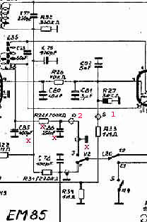
My expectation is more the 6 Volts on P1 and on P2, 50% off the Value on P1. This depends from the exact tuning of the set. For instance, you find on P1 8,6 Volts, by fine tuning on station the value on P2 must showed 4,3 Volts.
If not, test the four Components marked "x". Condensers should have an Insulating off more then 50 M Ohm, and the "R" 200 Kohm +/- 20%.
The capacity is only important from C85 = 400pf. You can bypassed some one! Only in this case, not on insulation, you must not soldered out!
If there all O.k. I think the only failure can bee on the switch U2 =AM/FM (marked on small diagram), ore an shorting in this whole Area, to ground.
If all this without failure, I don't now more, by using only the diagram, what can bee.
Let as wait what you find out.
if you have questions to this? ask me before.
Greetings from Hans
- Goldy Orders1 (37 KB)
To thank the Author because you find the post helpful or well done.
hot on the trail

Thank you for your reply.
Yes I agree you are right. That zone must be the hot zone.
I got -24V in (1) and -0,5V in (2). Resistor and caps were right.
But... I also found that some wires were changed.They are not as in schematic.
I think I have to read the schematic again and compare carefully the wires before I step ahead.
Meanwille there is another information: In FM,the maximum signal display in "Magic eye" doesn't correspond to the best tunning up. In the maximum signal display the sound presents much more distortion.
Best regards
Mário
To thank the Author because you find the post helpful or well done.
Bad wiring?

Hello Mario,
this here, (your text) is normally when U2 is not 50% from U1.
These conditions must be performed!
Your text:
Meanwille there is another information: In FM, the maximum signal display in "Magic eye" doesn't correspond to the best tunning up. In the maximum signal display the sound presents much more distortion.
I can tell you, to fix the Ratio Detector without special knowledge, is not possible.
You can ask someone because this.
I think, the only solution is, use an "Ohmmeter" and check all the wiring around the EABC80.

For the moment that's all what I can make for you.
Show me your results.
Hans
PS: Have you changed the EABC80?
To thank the Author because you find the post helpful or well done.
Some values

Hello Mr. Hans Knoll
I had not changed the EABC80 before. Now I changed it and I got no differences.
I got some values from EABC80 pins:
Pin 1 -1,3V
pin 2 -24V
pin3 -11V
pin 6 -0,4V
pin 7 0V
pin 8 0,5 V
pin 9 69 V
Without dessoldering, was measured, in resistor R33 and R34, 500 kOhms insted of 1000 kOhm.
Some wires are not intact but they are correctly placed as in schematic.
Meanwille, Thank you for your help and time.
Mário
To thank the Author because you find the post helpful or well done.
Finaly.

Hallo Mario,
maybe , you are disappointed?
About this here: Meanwille, Thank you for your help and time.
But. this results from you,
I got some values from EABC80 pins:
Pin 1 -1,3V
pin 2 -24V
pin3 -11V
pin 6 -0,4V
pin 7 0V
pin 8 0,5 V
pin 9 69 V
shows me,
there must be an interrupt between the 400pf Condenser and EABC80 pin #1 and #3 (redlines) 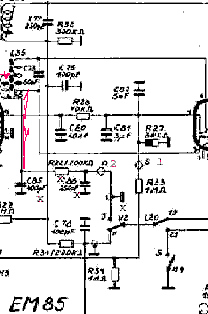
I don't now, why you have not follows this advice in Post 4?
I think, the only solution is, use an "Ohmmeter" and check all the wiring around the EABC80
This simple measurements , can bring out this failure.
O.K. if you are have endet, that's all right!
Hans
To thank the Author because you find the post helpful or well done.
In schematic is easier

Hello Mr. Hans Knoll
There is a lot of components here and a compact wire scenario. I am doing my best but I have no enough experience. For example I can't find out where is L36 pin, in IF component.
Sorry. Give me a little more time.
Best regards
Mário
To thank the Author because you find the post helpful or well done.
more infos

see this:
and this here:
and this:
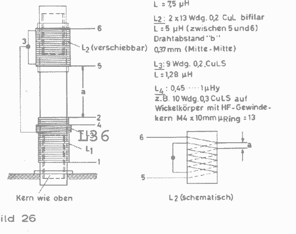
L36 is marked, this is not the Coil from Goldy, but standard Forming.
Hans
To thank the Author because you find the post helpful or well done.
OPEN CIRCUIT and no capacitor

Hello Mr. Hans Knoll
Thank you for your last post. The measurements you indicated were made. You were right, Results: OPEN CIRCUIT (pins 1 and 3).
Now I send you one diagram and one photo of the components connected to IF.
That's why I was not able to locate pin 3 of IF. As you can see only the 200kOhms resistor is there. The 400pF capacitor is not. 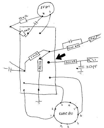
Does it means that L36 IF coil is open?
Best regards
Mário
To thank the Author because you find the post helpful or well done.
There is a 400pf!

Hello Mario,
you wrote:
That's why I was not able to locate pin 3 of IF. As you can see only the 200kOhms resistor is there. The 400pF capacitor is not visable.
I think or belive, the 400pf is locatet inside of the Filterbox.
This is usual, to prevend radiation of 10,7mcs in the Air and other stages of the Radio.
next: Does it means that L36 IF coil is open?
Yes sir! Thats right!
I have send to you on post6 a marked diagramm that shows the possibilty of an interrupt.
Now i make additional a new picture, that shows this again.
I hoppe you see what i mean? ;-)
Hans
To thank the Author because you find the post helpful or well done.
A hit in the mark

The coil wires inside of IF were well twisted but the varnish was not enough peeled. Soldering was insufficient.
Zero Ohms contact was acheived after pressing a little bit with my fingers.
Right in the target !. I hope you accept my respects.
Now I have to solder everything. I'll present the results later.
1 HOUR LATER:
YES! IT WORKS FINE. PURE SOUND!
TUNE INDICATOR IS NOW INDICATING THE RIGHT TUNE.
Thank you MR. Hans Knoll for your knowlege and great help.
How can I do to show you my thankfulness?
Yellow arrows : 1 - twisted wires are in the opposite side of this picture. See them in next picture. ; 2- the causer wire.
We can also see here the 400Pf capacitor.
Best Regards
Mário
To thank the Author because you find the post helpful or well done.
Finish!

Hallo Mario,
you ask me, How can I do to show you my thankfulness?
What can you do ? Work hard with all the Members of RM.org and bring everything to an good End like here!
Thank you also.
Greadings from Germany
Hans M. Knoll
To thank the Author because you find the post helpful or well done.
ORDER OF AID Radio Friends

Hello Mr. Hans Knoll
It was for pleasant me to follow this I dialogue with Mr. Mário. Not intending to abuse its good will and availability, by chance it does not know this radio?
I am a new member, and as pods to evidence here. I presented some works, are not many, but the time has not given for more. Thus it would desire that all the members made it. For example, I have a radio that it only has the model that is: SUPERSOM, has cabinet in wood the control knobs is in wood uses the valves: 6K7G, 6Q7G, 7SJ8G, 25L6G, 25Z6G, as pods to prove in annex, that if finds in this forum: Pods to help or some member me of the Rmorg, the year and the manufacturer?
THIS HELP IS FOR ALL THE MEMBERS
http://www.radiomuseum.org/dsp_forum_post.cfm?thread_id=8159
Thanks for the aid.
Júlio Branco, Lissabon
To thank the Author because you find the post helpful or well done.
Thanks for the quality

I am very positivley impressed with the quality and detail of this particular discussion. I am new to this forum and found it to be quite informative. I hope to have useful information to contribute some time in the future.
Thank you for your contributions,
Paul Pinyot.
To thank the Author because you find the post helpful or well done.
 Thread closed by a moderator. But replies can be made through a moderator.