
1619

|
|
|||||||||||||||||||||||||||||||||||||

|
Vus: 5910 Répondre: 3
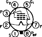
1619 (1619) Suppressor action
|
|
|
Joe Sousa
05.Jul.09 |
1
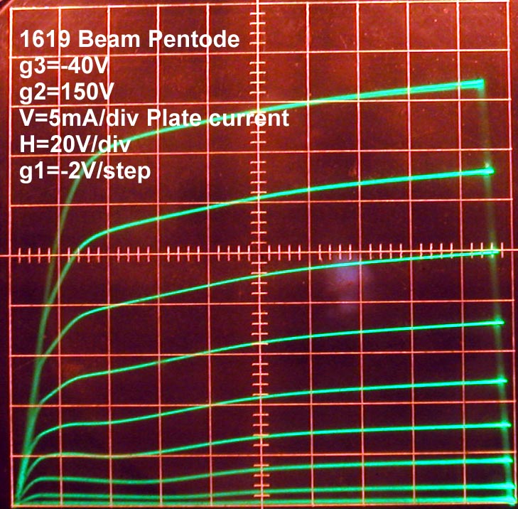
The following plots show the effect of bias voltage at the suppressor grid g3.
Further discussion of g3 action can be found at: http://www.radiomuseum.org/forum/app4120_gitter_1_3_parallel.html http://www.radiomuseum.org/forum/6f6eg_6f6eg.html Right-click and view or save these plots for higher resolution. Regards, -Joe |
|
Georg Beckmann
06.Jul.09 |
2
Hi Joe, in the negative saddle region ( picture down right ) a estimated a conductance of about 0.25mmho. If you build a parallel resonance circuit in the anode and have at least a Q of about 10, then you should get an oscillator without a feedback connection. Don't ask what it is good for, just pure science. :-) Georg |
|
Joe Sousa
07.Jul.09 |
3
Hi Georg, Your negative resistance observation combined with your tantalizing remark "Don't ask what it is good for, just pure science", to give me some inspiration during my drive to work this morning. I think that a frequency converter could be built around your idea of a plate oscilator. The following schematic illustrates a possible realization of the converter. The basic design constraints center around the choice of resonant LC tank circuit equivalent resistance at resonance for the local oscillator LC and for the for the IF load LC. This mode of oscillation was known as Dynatron mode. In this mode, the oscillation amplitude will rise until the average negative conductance seen by the tank circuit matches the positive conductance of the LC circuit (conductance=1/resistance). If this is met for the Local oscillator LC, then the IF LC can be chosen to have half the resistance, or twice the positive conductance at IF resonance, to guaranty that the IF tank will not oscillate. The factor of 2 is for a safety margin. Theoretically, the IF conductance just needs to be higher than the LO conductance. When oscillations start, it is possible that both coils will oscillate, but the tank with the higher impedance will dominate by lowering the average negative conductance to match it's own.
One possible disadvantge of this circuit is that the control grid gm is about half in the saddle region, as compared to the high voltage region of the plate. But this could be remedied by running a higher screen voltage. Another design constraint is managing the conductance of the LO tank circuit over the tuning range. This may involve adding a resistor in series or parallel, as needed. On the plus side, the screen grid still shields the input circuit from the plate oscillation voltage. I also added AGC control because of the intriguing possibility that this circuit could have an extended control over strong signals because it lowers gm and negative plate conductance, and therefor, the oscillation amplitude at the same time. An easier design that separates the Local Oscillator LC from the IF LC is the following realization:
This circuit takes advantage of the increase in gm from control grid to screen when the plate voltage is low. Neutralization could be added from the screen circuit to the input grid in order to increase the screen impedance at the IF frequency. But this neutralization is not needed for stability at the loop antenna. The screen still performs the shielding function for the LO oscillations at the plate. But I have a further question: Was this type of circuit, or something similar ever realized in the very imaginative designs of the short tetrode era around 1930? Perhaps the well known RM experimentalist Wolfgang Holtman has built something like this or would enjoy designing it. Regards, -Joe |
|
Wolfgang Holtmann
13.Jul.09 |
4
 Hello Joe
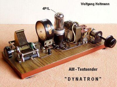
The idea of A. Hull’s DYNATRON was already in my mind some month ago. A very simple one-tube transmitter was "created", comprising some advantages:
- only one tube - rel. low distortion
- nearly no unwanted fm
- only one coil with a capacitor
Because the article has no direct relationship with the hf-mixer discussion here, it was moved to "Home Construction"
|


.gif)

Fin des contributions forum pour ce composant
| Mentions légales | Plus d'informations |