RTC1
|
|
|||||||||||||||||||||||||||||||||
|
Hits: 1009 Replies: 2
HOW TO TST RTC1 ?
|
|||||||||||||||||||||||||||||||||||||||||||||||||||||||||||||||||||||||||
|
Matthieu Testa
22.Apr.20 |
1
Hi, anyone able to tell me how to test RTC1 tube ? Regards
|
||||||||||||||||||||||||||||||||||||||||||||||||||||||||||||||||||||||||
|
Emilio Ciardiello
22.Apr.20 |
2
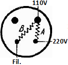
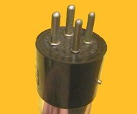
A simple continuity check can be done measuring the cold resistance between pins 2 and 3 - the two smaller pins - which could measure somewhere around 200 to 500 ohms. A more accurate test could be made applying 50 V rms between the same pins and measuring the current which should be around 300 mA AC. The test could aldo be done in DC. Emilio |
||||||||||||||||||||||||||||||||||||||||||||||||||||||||||||||||||||||||
|
Patrice Zeissloff
23.Apr.20 |
3
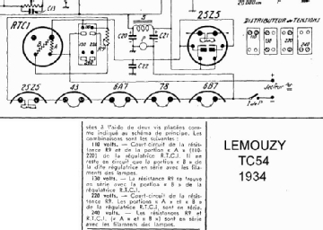
Hello, I have check my used RTC1 as in the circuit diagram of the Lemouzy TC54 radio "Resistor" A approx. 30 ohms cold is for approx. 110 V network with 5 tubes, eg 3 x 6.3V + 2 x 25V heating and 0,3 A heating current
"Resistor" B approx. 19 ohms cold, For 220V network the two resitor A + Bare serial switched with 5 tubes, eg 3 x 6.3V + 2 x 25V heating.
Note : In the Lemouzy TC54 a 70 ohms are used with "Resistor" A for 130 V Network and or with A + B for 240V network. Kind regards
Attachments
|
||||||||||||||||||||||||||||||||||||||||||||||||||||||||||||||||||||||||
End of forum contributions about this tube
| Data Compliance | More Information |


