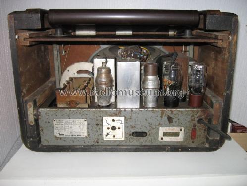
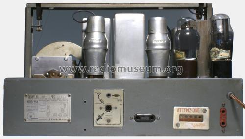
DL594
Irradio; Milano
- Paese
- Italy
- Produttore / Marca
- Irradio; Milano
- Anno
- 1938/1939
- Categoria
- Radio (o sintonizzatore del dopoguerra WW2)
- Radiomuseum.org ID
- 99366
Clicca sulla miniatura dello schema per richiederlo come documento gratuito.
- Numero di tubi
- 5
- Principio generale
- Supereterodina (in generale); ZF/IF 275 kHz
- Gamme d'onda
- Onde medie (OM), lunghe (OL) e 2 onde corte (2 x OC).
- Tensioni di funzionamento
- Alimentazione a corrente alternata (CA) / 110; 127; 145; 160; 220 Volt
- Altoparlante
- AP elettrodinamico (bobina mobile e bobina di eccitazione/di campo)
- Materiali
- Mobile in legno
- Radiomuseum.org
- Modello: DL594 - Irradio; Milano
- Forma
- Soprammobile con qualsiasi forma (non saputo).
- Annotazioni
-
Serie Super Lusso. Scala inclinabile in cristallo. Gamme d'onda: medie, lunghe, corte, cortissime.
Controllo di tono a 3 posizioni. Ingresso Fono.
- Fonte dei dati
- Guida Pratica Antique Radio II (2000)
- Bibliografia
- -- Schematic
- Letteratura / Schemi (1)
- Il Radio Libro (E.D. Ravalico) Edizioni Hoepli
- Letteratura / Schemi (2)
- Schemario di apparecchi radio a valvole (II edizione, D.E. Ravalico - Hoepli - 1945)
- Altri modelli
-
In questo link sono elencati 275 modelli, di cui 202 con immagini e 122 con schemi.
Elenco delle radio e altri apparecchi della Irradio; Milano
Collezioni
Il modello fa parte delle collezioni dei seguenti membri.
Discussioni nel forum su questo modello: Irradio; Milano: DL594
Argomenti: 2 | Articoli: 2
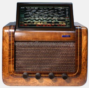
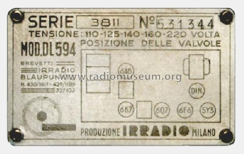
The Irradio DL594, produced in 1938, was proposed on the market at 1495 Italian Lire, i.e. at more than three times the price of the cheapest receiver on the market (Radio Balilla at 430 Lire) and 68% more than an economic receiver with comparable performance like the Magnadyne S35; it could thus be considered as an expensive set. The look of the DL594 is similar to that of many other Irradio sets and is characterized by an appealing large rotating dial glass based on a Blaupunkt design (patent Irradio/Blaupunkt N. 430/1417). Despite its cost and a construction based on a large use of quality components, the performance of the DL594 has never been considered as more than “honest”. This seemed to be the case also for the set considered in this note whose performance, after basic restoration operations, before performing a proper alignment, was quite modest. The set is endowed with 12 trimmers and it is, of course, reasonable to perform aligning operations with a precise knowledge of their role and not on the basis of “trial-and-error” procedures. The search for documents, however, did lead to misleading information. In fact the purpose of the trimmers of the DL594 is not specifically described in the available literature; on the book Il manuale del Radiomeccanico, by G.B. Angeletti, Vol. II, p. 377, it is however possible to find the description of the role of the trimmers in the Irradio DX5 and DX6 receivers (the same as in the DL594); unfortunately in this document the block concerning the oscillator has been exchanged with the antenna one (the role of one of the trimmers is also missing, we will see a possible reason in the sequel). To worsen the situation, the frequencies to be considered for 3 trimmers in the oscillator block are the same as those of the corresponding trimmers in the antenna block while the others differ so that, using this indication to align the receiver would lead to unacceptable results. Trying to associate the trimmers with their role as deduced from the schematic did not explain the role of one of the trimmers (the schematics report only 11 trimmers) and also the connection of the sections of the tuning capacitor remained partially unexplained. It was so decided to deduce the schematic from the restored set (serial number 531344) and this led also to find another error; the resistance inserted in the AGC feedback line has not the unusual value of 25 MΩ reported in all schematics but the more reasonable value of 2.5 MΩ (25 MΩ would lead to a time constant of 1,25 s while usual values are around 0,1 s). Also the values of some other components (padding capacitors and less important components) deviate from those of the available schematics but these last variations fall inside the differences often observed in sets produced at different times. The new diagram has been loaded on Radiomuseum.org and the remaining part of this note describes the connection of the sections of the tuning capacitor and the role of the alignment trimmers. The section of the schematic necessary for the considerations that follow is reported in Figure 1.
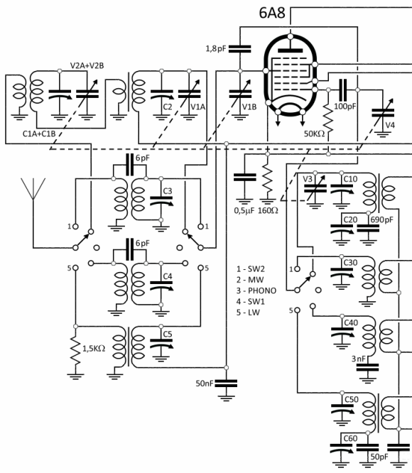
Figure 1 – Input and mixer stage of the DL594
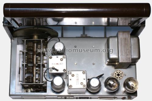
1) The tuning capacitor. Also this component is based on a Blaupunkt design. Its reduction gear is located on the back and is connected with the tuning knob, the flywheel and the scale index wheel by means of two auxiliary axes (a really complex design). At a first glance, it looks as endowed with eight sections (Figure 2).

Figure 2 – Tuning capacitor of the DL594
The electrically separated sections are, in fact, only 6; moreover sections V2A and V2B are connected in parallel (and used only in the MW input filter). Also V1A is used (in parallel with V1B) only in the MW band. The same can be repeated for V3 that is connected in parallel with V4 only in the MW band. V3 is not reported in the diagrams available in the literature.
2) Alignment trimmers. The trimmers reported Figure 1 correspond to the locations indicated in Figure 3.

Figure 3 – Position of the alignment trimmers
Note that the covers cannot be reversed so that the marking “IRRADIO” can be used as a reference key (on Il manule del radiomeccanico the references inside every block are correct but the blocks are exchanged since the oscillator and not the antenna block is reported as frontal). Note also that C1A and C1B are connected in parallel (this is a possible reason for the lack of indications concerning C1B on the previous book). The calibration frequencies are the following:

3) After aligning, by means of standard procedures, the I.F. channel (275 KHz) and the antenna and oscillator trimmers, the performance of the receiver changed drastically, particularly in the higher part of medium and long wave bands. While no measure has been performed on its sensitivity, the subjective impression and the A/B comparison with other receivers of similar class denoted a very good behavior. The response of the I.F. channel has then been measured by means of the procedure described in "Measuring the I.F. response in AM receivers”. The results are reported in Figure 4 where the normalized measured response is compared with the response of the Magnadyne SV3 at maximal and minimal bandwidth settings (regularly used as a reference because of its excellent performance). It can be observed that the overall shape of the SV3 responses is definitely better; the response of the DL594 is quite similar to the response of the less expensive Magnadyne S35.

Figure 4 – I.F. response of the DL594 (red) compared with the response of the Magnadyne SV3 at wide (blue) and narrow (green) bandwidth settings.
A check on the frequencies indicated on the scale in the MW band has, on the contrary, led to very good results with maximal errors under 2 KHz that looked as mainly due to mechanical hysteresis. Almost certainly this accuracy was an important design goal in order to take advantage of the dimension of the dial glass.
4) Concluding remarks. The Irradio DL594 is characterized by a large and accurate dial glass, by a very traditional circuit and by a performance comparable with that of other middle–class sets of the same period. The large elliptic loudspeaker looks more modern than expected and assures a comparatively good sound quality. The absence of a protection serial capacitor on the antenna input could be considered as questionable; the same could be repeated for the choice of assuring the polarization to the preamplifier tube only by means of a ground path through the sliding contact of the volume potentiometer.

Figure 5 – The restored DL594
Roberto Guidorzi, 27.Jan.14
Salve
sono in possesso di una IRRADIO MOD. DL 594 ma purtroppo senza scala parlante. Qualcuno mi può aiutare per averne una anche su lucido?
per risposte inviare una e_mail: claudioisosio[A*T]libero.it.
P.S.: pagherò per le spese del lucido e spedizione
Grazie
Claudio
Sosio Claudio, 08.Jun.11


