12VF26R Ch= TS-23A Standalone TV variant of model 12VF26R
Motorola Inc. (ex Galvin Mfg.Co. Chicago); Schaumburg (IL)
- Country
- United States of America (USA)
- Manufacturer / Brand
- Motorola Inc. (ex Galvin Mfg.Co. Chicago); Schaumburg (IL)
- Year
- 1950
- Category
- Television Receiver (TV) or Monitor
- Radiomuseum.org ID
- 229271
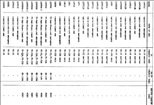
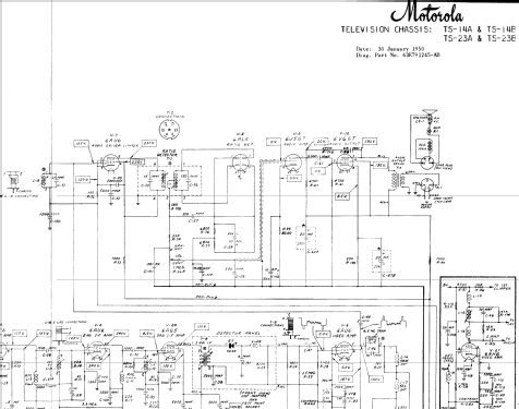
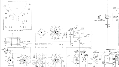


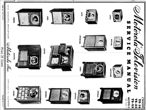


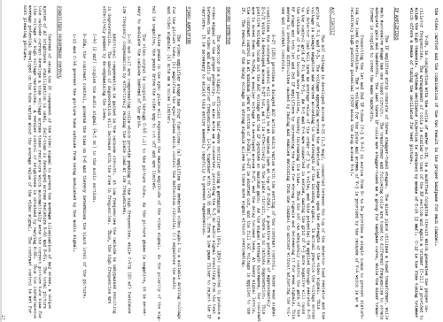


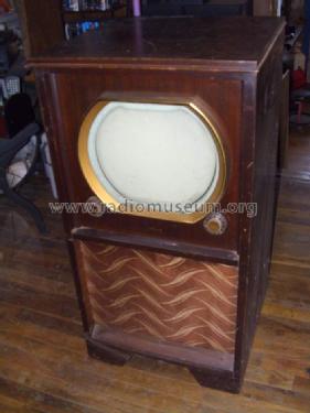
Photo courtesy of Nate Breeding

Photo courtesy of Nate Breeding
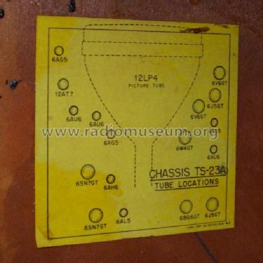
Photo courtesy of Nate Breeding
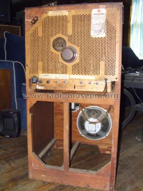
Photo courtesy of Nate Breeding
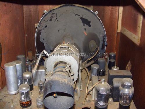
Photo courtesy of Nate Breeding
Click on the schematic thumbnail to request the schematic as a free document.
- Number of Tubes
- 19
- Valves / Tubes
- 6AG5 12AT7 6AU6 6AU6 6AG5 6AU6 6AU6 6AL5 6J5GT 6V6GT 6SN7GT 6J5GT 6V6GT 6AL5 6SN7GT 6BQ6GT 6W4GT 1B3GT or 1X2 12LP4
- Main principle
- Superhet with RF-stage
- Wave bands
- VHF incl. FM and/or UHF (see notes for details)
- Power type and voltage
- Alternating Current supply (AC) / 60 cycles, 117 Volt
- Loudspeaker
- 2 Loudspeakers
- Power out
- 4 W (undistorted)
- Material
- Wooden case
- from Radiomuseum.org
- Model: 12VF26R Ch= TS-23A [Standalone TV variant of model 12VF26R] - Motorola Inc. ex Galvin Mfg.Co
- Shape
- Console with any shape - in general
- Notes
-
The Motorola 12VF26R is a 12" b/w TV with US standard VHF Tuner channels 2 thru 13. Uses 19 tube TV chassis TS-23A and picture tube 12LP4. Console model with Red Mahogany wooden cabinet. TV chassis has Qty(2) Selenium Rectifiers used for power supply rectification and Qty(1) germanium diode video detector. Has Qty(1) electrodynamic 10" speaker and Qty(1) electrodynamic 5" speaker, both with field coils.
This particular model, the standalone TV variant of model 12VF26R, is not documented in Rider TV (Rider TV shows this model as a combination TV-radio-phono), nor in the Motorola datasheet. Existence of this model is documented by the pictures provided.
This model is part of a series of TVs produced by Motorola using the TS-14, TS-23, and TS-52 chassis. According to Rider TV vol. 5, the TS-14 chassis was used in 10 inch sets with 10BP4 CRT. The TS-23 chassis was used in 12 inch sets with 12LP4 CRT, and is identical to the TS-14 chassis except for the high voltage transformer. The TS-52 chassis was used in 16 inch sets with 16AP4 CRT, and is similar to the TS-14 and TS-23 chassis, except for the high voltage transformer, addition of a second 6BQ6 horizontal output tube, and the use of 25L6GT for the vertical output tube.
There are variations for each chassis type: For TS-14A and TS-23A, the 3rd IF tube was changed from 6AU6 to 6AG5. For TS-14B and TS-23B, the video amplifier tube was changed from 6AU6 to 6AH6, and an additional tap was added to the contrast control. Chassis TS-52 has the same changes as TS-14B and TS-23B.
See table in document under "schematics" for more detailed explanation of differences between models (cabinet style, TV chassis, radio chassis, and record changer).
- Literature/Schematics (1)
- Rider TV vol. 5
- Literature/Schematics (2)
- - - Manufacturers Literature (Motorola Datasheet 54P7000225)
- Author
- Model page created by Thomas Albrecht. See "Data change" for further contributors.
- Other Models
-
Here you find 4595 models, 2962 with images and 4093 with schematics for wireless sets etc. In French: TSF for Télégraphie sans fil.
All listed radios etc. from Motorola Inc. (ex Galvin Mfg.Co. Chicago); Schaumburg (IL)