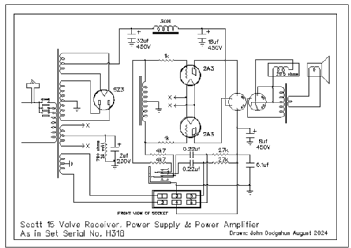
All Wave (Allwave) 15 (Chrome CHASSIS)
Scott Radio Labs.(E.H., Transformer); Chicago (IL)
- Pays
- Etats-Unis
- Fabricant / Marque
- Scott Radio Labs.(E.H., Transformer); Chicago (IL)
- Année
- 1934
- Catégorie
- Radio - ou tuner d'après la guerre 1939-45
- Radiomuseum.org ID
- 55360
Cliquez sur la vignette du schéma pour le demander en tant que document gratuit.
- Principe général
- Super hétérodyne (en général)
- Gammes d'ondes
- PO et OC
- Tension / type courant
- Alimentation Courant Alternatif (CA) / 110 Volt
- Matière
- Boitier métallique, lampes visibles
- De Radiomuseum.org
- Modèle: All Wave 15 - Scott Radio Labs.E.H.,
- Forme
- Chassis (pour intégration dans meuble)
- Remarques
-
The Scott Allwave 15 was introduced in 1934 and was designed to replace the earlier Scott Allwave 12. New features were the addition of a tuning meter driver tube, BFO, and push pull audio driver stage. The audio output was increased by replacing the push pull 45 valves with 2A3’s. There were two versions of the Allwave 15, an early version which had a 55, 2nd detector tube set up as a half wave detector and a late version which had the 55, 2nd detector tube set up as a full wave detector.
Frequency Ranges:
BC Band (White Band)...540 kHz - 1500 kHz
SW-1 Band (Green Band)...1.5 MHz - 4 MHz
SW-2 Band (Red Band)...4 MHz - 10 MHz
SW-3 Band (Purple Band)...10 MHz - 23 MHz.
- Source extérieure
- Ernst Erb
- Source du schéma
- Rider's Perpetual, Volume 15 = 1947 and before
- Littérature
- E.H.Scott Radio Collectors Guide (1925-1946)
- Schémathèque (1)
- Australian HRSA Radio Waves, January 1997, Page 9
- D'autres Modèles
-
Vous pourrez trouver sous ce lien 200 modèles d'appareils, 125 avec des images et 50 avec des schémas.
Tous les appareils de Scott Radio Labs.(E.H., Transformer); Chicago (IL)
Collections
Le modèle All Wave (Allwave) fait partie des collections des membres suivants.


