
117N7GT

|
|
|||||||||||||||||||||||||||||||


|
Hits: 4081 Replies: 1
Holiday Greeting
|
|
|
Joe Sousa
23.Dec.09 |
1
Fellow Radiophiles, I wish you all a very Happy Holiday, in peace and enjoying the good company of family and friends.
A special thanks for the tireless efforts of our founder, and most active member, Mr. Ernst Erb. Through his vision and steadfast work, we have all made world-wide connections in our shared interest in old radios. We have all learned from each other, and expanded our vistas. The radios reflect their country's histories and different ways to imagine an engineering solution. I thank and applaud the tireless and thankless work of administrators and moderators. I also thank and applaud the generosity with which so many of our more talented and learned members have shared what they know. Many contributions were made with amazing professional quality. So many contributions are not available anywhere else, but can be enjoyed by the world-wide public. With warmest regards, -Joe
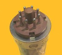
One such example is the Holiday decoration of this post. It was inspired in an old high voltage 4mH choke that I picked up at a radio meet, because it reminded me of a Christmas tree. My friend Ron Roscoe contributed the 1933 Radio News magazine where I found this ad for the choke. This decoration also serves to illustrate the usefulness of the 117N7 power pentode and rectifier for simple stand-alone low cost applications. The Pentode works as a Class C 400kHz RF oscillator with the green choke providing a high voltage output (~800Vp-p, 0.4mA) to light up two series strings of tiny NE1 neon bulbs and two100k ballast resistors. There is also a blue fluorescent bulb in series with these two strings, serving as the tree-topper. The 4mH choke is not explicitly tuned but was found to resonate near 400kHz under the neon bulb load. The specifed 1pF distributed capacitance suggests an intrinsic self-resonance of 2.5MHz. I added two additional coils with enamelled AWG#22 magnet wire.One coil has 84uH of inductance, and is tuned with a 1000pF to 400kHz in the plate circuit. The other coil has 12.5uH of inductance and applies positive feedback to the control grid. I measured the short circuit inductance of the plate coil as 50uH, thus suggesting fairly tight coupling to the other coils. (Short circuit inductance for a coil is measured with the other coils shorted) The following schematic includes development notes and intermediate results. The final results are circled in blue.
I added a green fluorescent neon bulb to monitor the screen voltage at 99VDC. A red incandescent bulb helps regulate cathode current, and also serves as loading indicator. It glows more brightly under heavier load. This was useful when experimenting with various numbers of neon bulbs at the output. The decorative usefulness of these bulbs was also a factor in my choice. The 120uF supply bypass capacitor came from a single-use film camera, but a 0.22uF film capacitor was needed to protect the electrolytic from excessive RF currents. At one point, the 1000pF capacitor in the tank circuit was tied between plate and ground, instead of plate and Bplus. The 1A circulating RF current in the resonant series path of 1000pF+120uF+84uH was enough to blow up the electrolytic cap. I fixed that with the additional 0.22uF film cap, but eventually, I moved the 1000pF directly in parallel with the resonating 84uH coil.
The plate voltage waveform was probed with a 10X probe, and the pulsed plate current was sampled with a Tektronix P6020 current probe. I could have used a 1Ohm resistor to sample the current on the ground return of the 0.22uF supply bypass cap, but I had the P6020, so it was more convenient. Note that this is the current that the tube pumps during every cycle into the resonant 84uH//1000pF tank circuit at the plate. This is not the circulating 1Ap-p sinewave current that flows inside the tank circuit. One of the defining characteristics of Class C operation is the complete cutoff of tube current during most of the RF cycle. In this case, the duty cycle is only 20%. The high Q of the resonant tank absorbs the pulse energy and reshapes it as the lovely sinewave that I probed at the plate. The turns ratio of 4:1 from the plate tank to the control grid winding guaranties plenty of negative overdrive for cut-off. The control grid voltage wave is in opposite phase to the plate voltage shown in the scope photo. The grid swings from +4V to -50V, while the plate simultaneously swings from +30V to +260V. Just for fun, I simulated this oscillator in Linear Technology's free LTSpice IV. The tube models came from the LTSpice Yahoo newsgroup. The simulator is available for free at www.linear.com.
A couple more views of the decorative scene. The base was made from a recycled test card from work, at Linear Technology. The open circle under the tree/choke is where a silicon wafer probe ring would sit. The housing is just black foam board for enhanced contrast. The green bulb on the left indicates screen voltage, and the little red bulb in front of the 117N7 indicates cathode current. Please feel free to use your imagination to interpret what you see. Above all: Enjoy!
-Joe |
|
Todd Stackhouse
24.Dec.09 |
2
...That is really something. Nice work! ...I can't add anything to what Joe has said; he's said it very well. I would only like to add my own wishes to the Radiomuseum community (which I've also done for the German-speaking members) for all the best this Christmas and in the coming new year. Sincerest holiday greetings! Todd
|


End of forum contributions about this tube
| Data Compliance | More Information |