
41MP

|
|
|||||||||||||||||||||||||||||||||||||||


|
Visite: 3239 Risposte: 6
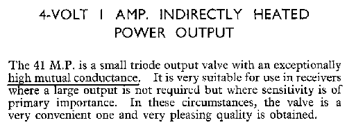
41MP, triode connected tetrode, please explain
|
|
|
Nicolaas van Dijk
10.Mar.16 |
1
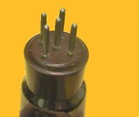
I have a 41MP triode, but looking at the interior, it is a tetriode. The second grid is internally connected to the anode via a small spiral. may be just to prevent mechanical stress or it may be a resistance. Can anybody tell me what the reason is for this construction? Allegati |
|
Wolfgang Holtmann
10.Mar.16 |
2
You are right, the second grid is tied to the anode. Here is the explanation by the manufacturer:
In fact, with this trick the anode get's closer to the control grid and the claimed Mutual Conductance Kind regards.
|
|
Jacob Roschy
11.Mar.16 |
3
I don't understand what's the advantage to mount a second grid close to the control grid and tie it to the anode, then mount the anode itself just as close to the control grid ? Best Regards, Jacob |
|
Dietmar Rudolph † 6.1.22
11.Mar.16 |
4
The advantage of this construction may be threefold.
Best regards, Dietmar |
|
Nicolaas van Dijk
12.Mar.16 |
5
Dear Dietmar I respomd to you, but really like to thank all of you for the answer. The reasons seem clear and indeed, the valve has a very high transconductance. Perhaps I like to try the 41MP one day in an amp to see how it behaves, interesting regards |
|
Wolfgang Holtmann
12.Mar.16 |
6
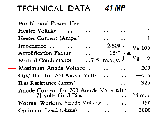
Another advantage -due to the high Mutual Conductance- an additional lf-preamplifier may be obsolete. On the other hand, The reason for this is given in the Technical Data below:
Because of the little distance of the second grid (at anode level) in respect to the control grid, the anode voltage is limited to 200 volts! Kind regards |
|
Jacob Roschy
13.Mar.16 |
7
Since this design was not continued in newer types, it may not have fulfilled as was expected. As only 12 models used this tube, it could be considered as a non-starter. The reduced capacity between grid and anode may not be of much importance for an audio output triode. While the heat dissipation of the anode can be increased, the thin windings of grid # 2 are even more endangered for overheating, hence grid # 2 is connected to the anode via a spiralised resistor wire as current limiter. Best Regards, Jacob
|
Fine delle discussioni nel forum su questo valvole
| Conformità dei dati | Ulteriori informazioni |