6F6EG
|
|
|||||||||||||||||||||||||||||||||||||
|
Hits: 8349 Replies: 6
6F6EG (6F6EG)
|
|
|
Jacob Roschy
22.Mar.08 |
1
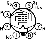
Apparently the tubes 2A5E, 18E, 42E and 6F6EG are special versions of 2A5, 18, 42 and 6F6G. They distinguish against their normal versions in that way, as their grid # 3 (suppressor grid) is connected to grid # 1 (control grid), instead of being connected with cathode, as usually. In Europe the tube company Tungsram followed this fashion by releasing some tube types of the same peculiarity and called them "Tetraforte". Known type were at least the PP415 as direct heated type and the APP4120 as indirect heated tube. Apparently, both the PP415 and the APP4120 were also available as normal penthodes, with g3 connected to cathode. It would be interesting to find articles and other information about these tubes in contemporary literature of the early 1930s. By now, we know very little, with exception of some schematics and base diagrams, where the g3 to g1 connection is visible. Best Regards , Jacob |
|
Torbjörn Forsman
03.Jul.09 |
2
This interconnection can also be found in 6V6EG from the swedish valve manufacturer SER. Another strange feature of the SER 6V6G and -EG is that they are penthodes, not beam tetrodes as all ordinary 6V6. It seems that the electrode system is identical to that of the 6F6G except for the cathode and control grid. Another Tungsram valve that i have found with G3 connected to G1 is the PP430. |
|
Thomas Albrecht
04.Jul.09 |
3
Jacob and Torbjörn, As I was working through Philco models, it became clear that "Philco-Tropic" radios, which were a line of radios marketed for export to harsh environments, used "E" tubes frequently. At first, I thought these were simply some kind of ruggedization, but seeing your comments above, I've looked at the schematics for many of these models to see if there is evidence of different wiring on the "E" tubes used by Philco. The results of my study are confusing. The "Philco-Tropic" models in the late 1930s and early 1940s have model numbers with the model year followed by 7xx. For example, model 39-770 is a Philco-Tropic model. The text in the Philco 1939 RMS Yearbook says about this model: The Philco-Tropic radio is particularly recommended for locations where super reception of short wave is necessary and where the radio and the cabinet are exposed to extreme conditions. The receiver is especially constructed to withstand decay, spoilage and deterioration caused by extreme conditions of humidity, heat, salt air and cold; and to stand up under the most severe tropic weather conditions. The chassis are heavily plated, making it impervious to salt air, rust and corrosion. The various parts, such as coils, condensers, chokes and transformers, are treated with special wax that will withstand very high temperatures. In addition the wax is treated with chemicals which repel rodents and insects. The cabinet is treated with a special sealing compound which protects against moisture and heat. In the list of tubes, the following comment is made: Several of the above tubes are interchangeable with "E" type tubes; refer to schematic diagram for locations. The schematic shows the following tubes as "E" types: 6K7G 6J8G 6F6G Looking at the schematic, there is no apparent difference in the wiring for 6K7EG, but the 6F6EG shown in the schematic does indeed have G3 connected to G1, rather than to the cathode (normal for 6F6G). 6J8EG has G3 brought out to a separate pin, instead of connected to the cathode (normal for 6J8G). Unfortunately, things are not consistent in the Philco schematics. For example, model 41-788 shows 6V6EG tubes, but shows them with G1 and G3 internally connected. In contrast, model 40-780 shows 6V6G* (with * indicating "E" tubes), and shows G3 brought out to its own pin (no internal connection) and wired to a connection that is not common with either the cathode or G1. A standard 6V6G has G3 connected internally to cathode. Similar situation for 35A5E, which for model 40-710 shows a separate pin for G3, while for model 41-705, G1 and G3 have an internal connection. For model 40-2710, G1 and G3 are connected externally. An even more confusing situation is shown for type 25L6EG, with model 40-756 showing a separate pin for G3, model 41-759 showing G1 and G3 internally connected, and model 39-711 showing G3 internally connected to cathode. A standard 25L6G has G3 connected to cathode. For the following output tubes, G1 and G3 are always internally connected when shown on the Philco schematics I looked at: 41E 42E 7B5E 6F6EG 6K6EG Philco used "E" tubes for various RF, mixer, and IF tubes as well (as you can see above in the model 39-711 example). I haven't yet done an extensive comparison on those yet to check for consistency on Philco schematics. Given the differences in wiring, I wonder if standard and "E" tubes really were interchangeable in Philco radios? Is the connection of G3 not so important, whether to G1, cathode, or something else? Does anyone understand what Philco was doing with all the apparent conflicts on their schematics regarding the wiring of "E" tubes? Best regards, Tom |
|
Joe Sousa
04.Jul.09 |
4
This is a very interesting thread pointing out possible uses for g3, which is usually grounded. I have never come across a power beam tetrode with separate g3 connection, so I am dying to find out what effect g3 has on the curve family. I just made a post showing higher mu and output impedance for the DF97 when g3 is biased at 7.4V. When I applied a positive bias to g3 of the Russian subminiature 1j37b the low voltage knee moved markedly to the right with negative voltages. Much of the design effort of a beam tetrode consisted in shaping the knee region with g3, so it will be ver interesting to see how the curve family can be reshaped with a bias at g3. The Philco 40-780 that Tom mentions has g3 of both 6v6g output tubes tied to the speaker output, persumably for negative feedback. Now I want to find one of these tubes and curve trace it. Perhaps another RM member already owns one of these tubes and could do the curve-tracing and post the results. It could be that the only way to find one of these tubes is to take it out of one of the radios that Tom mentioned. Tom, do you have one of these tubes? Regards, -Joe |
|
Thomas Albrecht
04.Jul.09 |
5
Hi Joe, Unfortunately I have never seen a Philco "E" tube in real life. They seem to have only used them for Philco-Tropic export models, which I have also never seen. Most Philco-Tropic models are not shown in Rider, which further establishes the idea that they were mainly sold outside the U.S. Since RMorg has a lot of international participation, perhaps someone outside the U.S. has a Philco-Tropic radio or has an "E" tube from one. Otherwise it sounds like there are some other sources of "E" tubes in Europe. Best regards, Tom |
|
Jacob Roschy
04.Jul.09 |
6
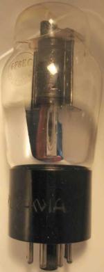
First I found the parallel connected g1 + g3 on this Sylvania 18E :
Then, some time later I discovered this Tungsram APP4120, also with parallel connected g1 + g3 :
Tungsram offered their tubes having this feature as "Tetraforte"- tubes, claimed "higher amplification by double control". Tungsram didn't even mark their "Tetraforte" versions at the tube designation ! @ Joe: at least there are 2 beam power tetrode tubes I know with separate g3 connection, the 1619 and the 6BW6 . PS: I add on the 2E30 Best Regards , Jacob
|
|
Torbjörn Forsman
04.Jul.09 |
7
One additional beam power tetrode with separate G3 connection is the PL81 / 21A6 (and of course its 6.3 V sister valve EL81 / 6CJ6). An interesting use for this feature can be found in the hungarian tv Videoton TA-675 , where a PL81 is used as line output valve and its G3 is connected to the AGC line. So, the G3-K path of the PL81 is used as an AGC delay diode.
|
End of forum contributions about this tube
| Data Compliance | More Information |


