
6X6

|
|
|||||||||||||||||||||||||||||||||||||


|
Hits: 6150 Replies: 0
Substituting the rare two-cathode 6X6
|
|
|
Jacob Roschy
19.Dec.11 |
1
A number of Canadian De Forest and Rogers-Majestic radios from 1937 to 1940 were fitted with the improved two-cathode version of the 6X6 magic eye tube, to create two wider shadow angles, which improves the utility of this eye tube considerably, as compared to the then usual eye tubes with only a single and narrow shadow angle as the 6E5. Unfortunately only very few of these two-cathode 6X6's have survived. One can substitute them by a normal single-shadow angle 6X6 version or by a British Y63 or Vi103, but the unique feature of the two-cathode 6X6 is lost then. However, there is a chance to achieve virtually the same two wide-shadow angles display of the two-cathode 6X6 by substituting it by a 6AF6G and an additionally control triode, such as the 6L5, 6J5 or 6C5.
The diagram above shows how the tubes 6AF6 and 6L5 can substitute the 6X6 in many Roberts-Majestic radios. An input voltage of -14...15 V at the triode grid results in full output of the 6AF6's shadow angles, which can easily be achieved by receiving stronger stations. The input voltage divider resistors R18 and R19 may be altered for proper indication, e.g. by matching them to full output by the strongest incoming station. It may be advantageous to replace R18 and R19 by a 1 MegOhm trimpot for easier adjustment. If the radio has two 2X3's as rectifiers, then there is a good opportunity to accommodate the 6L5 control triode. One can remove these 2X3's and replace them by one 5Y3G/GT, while the one spare socket will then be used for the 6L5.
Both of these pictures show a comparison of the true two-cathode 6X6 (top) to the 6AF6 (below), controlled by a 6L5. That clearly proves the 6AF6 as a fully equivalent substitute of the 6X6.
The diagram above shows the test circuit used to simulate the conditions of the Roberts-Majestic radios using the 6X6.
This animated picture shows a sweep from 0 V to -15 V control voltage at the grid of the 6L5 control triode. Getting out even more of the 6AF6 ! If you use the 6AF6 anyway, why not trying to get the most out of it ? There is the possibility to drive both indicating sections successively rather then drive them in parallel as usual, which gives a much better resolution of the indication range. The indication range is extended over both sections successively. Weak signals are only displayed on the first sector. The second sector displays the stronger signals and starts not before the first sector is fully closed.
See more under :
(Proof read by J. Sousa. 12-17-2011) |


|
Hits: 3849 Replies: 2
6X6 functionally different from other round eye tubes
|
|
|
Joe Sousa
07.Apr.11 |
1
Fellow Radiophiles: The 6X6 pinout and function have been incorrectly reported shortly after it's introduction in 1937. [Ludwell Sibley, “A Bit More on Rogers,” Tube Collector, April 2000, p. 16 (6X6 tube)] The 6X6 is not functionally equivalent to other round eye tubes like the 6G5/6E5 or 6U5. Ed Lyon has also reported on this error [Ed Lyon, "Wide-Shadow-Angle Tuning Indicator Tubes", Radio Age, January 2003, p. 7]. The 6X6 has a very wide deflection angle between 0o with the eye closed, and nearly 180o, with the eye wide open. Ed's article also explores in detail how to widen the 90o deflection angle of the very common round eye tubes 6G5/6E5, to 160o, with the addition of an external triode, such as the 76. Ed's application follows an RCA application note from 1937. This application note was also published in Radio World, February 1938 p. 19. The functional difference of the 6X6 from other round tuning eye tubes is that the input triode has an independent cathode that may remain grounded with respect to the AVC control signal, while the CRT section has a separate cathode that is optimally biased at a higher voltage (>+45V) for a wider deflection angle. Keeping the CRT cathode at pin 6 in the 6X6 biased at a high voltage makes it possible for the deflection anode to be pulled below the CRT cathode, toward the triode cathode, which sits at ground level. When the deflection anode at pin 3 is pulled below the CRT cathode at pin 6, the delection widens to nearly 180o. The correct 6X6 OCTAL pinout that appears frequently in Rogers-Majestic radio schematics is: 1-NC Regards, -Joe |
|
Jacob Roschy
07.Apr.11 |
2
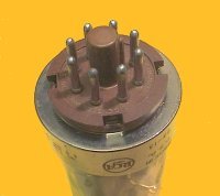
Dear Joe, apparently there are two different versions of 6X6 eye tubes existing, - the one you are talking about versus the one shown here on the RM page. This red painted Haltron 6X6 is of the same design as other single-shadow-angle tuning indicators such as the 6E5 and has just the same narrow deflection angle. It can't impossibly have an independent cathode on its input triode, since pin 6 is omitted on the base, as clearly visible at the picture. I can simply replace the Haltron 6X6 by a Vi103 without any remarkable difference. Best Regards, Jacob |
|
Joe Sousa
02.May.11 |
3
Fellow Radiophiles: The Rogers 6X6 mystery stimulated an international and intercontinental search that finally revealed the history of the this exceptional round eye tube. This exchange included Ed Lyon, Ludwell Sibley, Brian Belanger, Jacob Roschy, Howard Mariotti, Roy Johnson, Bill Courtright, Lea Barker, Gordon Rabjohn and Steve Rizewski. Jacob Roschy has updated the Rogers 6X6 tube page with these findings. Steve Rizewski lent his rare specimen of this tube to fellow Ottawa Vintage Radio Club Gordon Rabjohn for photographing and electrical investigation. Lea Barker was Ed Lyon's link at the Ottawa Vintage Radio Club. I include here a converted power point presentation that Gordon Rabjohn kindly sent to report his findings on the 6X6G. The 6X6 Gord Rabjohn
6X6 was tested
Triode has zero emission. I suspect an open cathode or maybe grid.
Pins were resoldered with no improvement.
However, we can prove conclusively that pin 6 is used for the indicator cathode. If it is disconnected, the target goes dark.
Full View
  Hard to see, but the indicator cathode is brought down to the pinch with a fine “insulated” wire, looks like a filament! Hard to see, but the indicator cathode is brought down to the pinch with a fine “insulated” wire, looks like a filament! 
Socket
 
Markings
  .gif) Thank you all for the contributions to solve the 6X6 mystery. Regards, -Joe
|
End of forum contributions about this tube
| Data Compliance | More Information |