AX50
|
|
|||||||||||||||||||||||||||||||||||||
|
Hits: 3505 Replies: 1
AX50 (AX50) Quecksilberfüllung für welchen Zweck?
|
|
|
Tobias Münzing
04.Jun.08 |
1
Liebe Sammlerkollegen, Ich halte in den kommenden Wochen ein Referat im Profilfach Elektrotechnik über Röhrenverstärker. Dabei bespreche ich im einzelnen die Funktion des Philips EL6420. Irgendwann sei es vom Lehrer oder von den Schülern kommt die Frage warum "leuchten" die Röhren so blau "weil sie Quecksilber enthalten" und warum???? Fragen über Fragen die ich nicht ungelöst lassen möchte. Deswegen bitte ich darum das die Wissenden mich Unwissenden wissend machen. Mit freundlichen Sammlergrüßen Tobias Münzing |
|
Rüdiger Walz
05.Jun.08 |
2
Gasfüllungen in Röhren wurden zur Verringerung des Innenwiderstandes eingesetzt. Neben der Elektronenleitung hat man hier auch Stromleitung durch ionisierte (positiv geladene) Gasmoleküle. Diese entstehen durch Zusammenprall von Gasatomen mit Elektronen hoher Geschwindigkeit. Hiebei werden in der Elektronenschale der Gasmoleküle Elektronen so angeregt, dass sie die Atomschale verlassen und ein positiv geladenes Gasion zurückbleibt, dass sich entsprechned der angelegten Spannung zur Kathode bewegt. Das beim Zusammenstoß enstandene freie Elektronen kann selbst wieder mehr als ein weiteres Elektron freisetzen, es entsteht ein Lawineneffekt. Daher benötigt man eine gewisse Zündspannung in solchen Röhren um erste Elektronen aus den Gasmolekülen freizusetzen oder man verwendet zur Absenkung der Zündspannung eine Glühkathode, die genügend Elektronen erzeugt. Dieser Mechanismus funktoniert nur in einem gewissen Gasdruckbereich. Bei zu hohem Druck erreichen die Elektronen nicht die erforderliche Geschwindigkeit bevor sie mit einem Gasmolekül zusammenstoßen, bei zu geringem Druck treffen Sie auf keine oder zuwenige Gasmoleküle, es entsteht kein Lawineneffekt. Vorzugsweise wurden bei Gleichrichterröhren und hier vor allem bei Niederspannungskleingleichrichtern für die Akkuladung Quecksilber verwendet. Es hat einen definierten genau passenden Dampfdruck und ionisiert leicht. Man kann in den Kolben einige Tropfen Quecksilber (Hg) geben und hat dadurch ein Reservoir, wenn Hg an den Metallteilen der Röhre absorbiert wird. Bekannt in Großanwendungen sind die mehrarmigen großen Gleichrichter in denen eindrucksvoll im Betrieb ein Plasmapunkt auf dem Quecksilbersee tanzt. Man verwendete für Gleichrichter auch Edelgase wie Neon, Argon oder Krypton (z.B. RGN 1500). Diese leuchten rötlich. Man erkauft sich den geringeren Innenwiderstand durch eine höhere Abnutzung der Kathode, die durch die positiv geladenen schweren Ionen bombardiert wird. Zudem sind die Kennlinien solcher Röhren temperaturabhängig, weshalb man bei Verstärkerröhren von den Gasfüllungen abging (siehe Liebenröhre). Blaues Leuchten bei Verstäkerröhren deutet auf Gasausbrüche von Sauerstoff aus der Anode hin und sind nicht beabsichtigt. Sauerstoffionen leuchten ebenfalls blau (ein etwas anderer Farbton als Hg). Wer sich mit dem Regenerieren von Röhren beschäftigt, kennt das grüne Leuchten von Bariumionenen aus dem Gettermaterial. Rüdiger Walz |
|
Hits: 6350 Replies: 17
AX50 (AX50)
|
|
|
Perica Adnadevic
07.Mar.08 |
1
Hello dear old electronic friend, I have one problem with this tube.I want to made an amplifier with tubes F2a11 and as rectifier tube I want to use AX50.Problem is with delaying anode voltage(preheating increase tubes life) .Is it possible to turn on anode voltage after a minute(with time relay), and is it safe for rectifying tube-it is gas tube(mercury)?Does anybody have an idea about this thematics).Thanks.Peter. |
|
Emilio Ciardiello
07.Mar.08 |
2
Dear Perica, a thermal delay relay, Amperite 6N090 or similar, can be used to have the required delay. The gas rectifiers are commonly used with chocke input filters: you should use a good relay, the coil driven by the thermal relay, the contacts wired between the rectifier cathode and the filtering coil. The buffer relay avoids any voltage and current limits with the contact ratings of the thermal relay. Regards |
|
Perica Adnadevic
09.Mar.08 |
3
Thanks Emilio, I still have some questions about this problem.How much mcF I can use after the choke,and can I use two LC filters with large capacitor after a second choke(about 330mcF).Is this safe for gas rectifier. One old electroengeneer told me that delay relay is not good for gas rectifier because heat cathode can be destroyed after switching anode voltage(spark effect or something like that, I don't know-I'm medical Dr).Do You know where I can find literature about this problem,because this beautiful tube AX50 is hard to find nowaday, and I do not want to destroy few pcs I have.Thanks.Peter |
|
Emilio Ciardiello
09.Mar.08 |
4
Dear Peter, usually the life of gas rectifiers may be increased when heaters are allowed to reach their operating temperature before applying anode voltage. For this reason some kind of delay is required when using these devices. However there are two major problems to be kept in consideration when designing the power supply: The first one is due to the low internal resistance of gas rectifier: the circuit around must be designed to safely stay within the peak values given by the manufacturer for the tubes. The limitation of the peak current is one of the reasons why an inductive input filter is preferred when working with gas rectifiers. If you need a very low ripple, a double section LC filter can be used. The capacitance value depends upon many parameters, but usually is quite low, in the order of tens of microfarad. The second problem derives from power failures, if long enough so that the rectifier heater is allowed to cool. When the power rises again, the thermal delay relay, if used, could still be warm: in this case the delay could be very short, if compared to the nominal value, and the anode voltage is applied before the rectifier has reached its operating temperature. To avoid this, one set of contacts of the auxiliary relay is used to disconnect the heater of the thermal relay once the delay cycle is ended. A good reference on this item can be the Radio Engineering Handbook by Henney. If you need, I can try to send copy of the related pages. Regards, Emilio |
|
Ernst Erb
11.Mar.08 |
5
Dear Peter I deleted your post because we should not put in eMail-addresses: As you see below of a post, members can answer you per eMail directly anyway ;-) |
|
Perica Adnadevic
13.Mar.08 |
6
Hello Emilio, as I saw now Ernst Erb deleted my reply to this message,so there is what I wrote to You. I'll be greatful if it is no much trouble for You to send me a copy pages from a Henney's book.Again thanks for many useful informations about this thematics.I'm on the begining in this aeria, but with energy and great will to learn. P.S. sorry for my bad english.Sincerely,Peter. |
|
Emilio Ciardiello
14.Mar.08 |
7
Dear Peter, I am going to attach the draft diagrams of either a power-on delay circuit, using a DPDT auxiliary relay, and of a generic double cell LC filter.  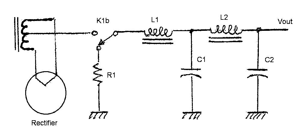 For the design of the LC filter, values of the choke coils and of the capacitors can be readily calculated once some parameters have been defined. Just considering the first section, you should determine the minimum or critical value of the input coil: to do this, you must know the DC voltage and the maximum load current. The value, in Henries, is given by the ratio between the cell output, in Volts, and by the maximum DC current drawn through the filter, in Amperes. Then you can find the proper value of capacitance for acceptable ripple. Unfortunately graphs given in U.S. books are referred to 60Hz AC main; at 50Hz the ripple is somewhat higher. For large value of capacitance, you can assume that the ripple is the ratio between the inductive (XL) and the capacitive (XC) reactance. To further reduce the ripple, a second LC cell may be added as shown by the following graph from Henney.  In this case, the output ripple will be given by the formula:  I will send you the copy of the pages from Henney, related to this thread. Please, give me few days to do the job. |
|
Perica Adnadevic
14.Mar.08 |
8
Thanks Emilio, there is no need to hurry abot this.Whenever You send to me I'll bee greatful. Thank You again.Sincerely,Peter. |
|
Emilio Ciardiello
16.Mar.08 |
9
Dear Peter, I forgot to say that, when calculating the minimum value for the inductance, you should consider the worst case conditions, both for the voltage and for the load current. The voltage should be increased according to the ratio between the maximum and the nominal values of the AC main in your Country. The load current depends upon the type of amplifier. As empiric rule you can use a good safety factor increasing Lmin value at least 1.5 times. Emilio |
|
Perica Adnadevic
25.Mar.08 |
10
Thanks Emilio for all the data You provide to me.This problem is not simple as I tought.There is so many things Youy must know if You want to made a respectable quality amplifier.Now I can say that,maybe, the most important part of the amplifier is good rectifier.Logicaly now we can say that good music ,besides output tubes, cames from the good rectifier. Problems Emilio and I talk about is also how to protect rec. tubes(AX50) from overload,and how to increase tube life with delayed anode voltage.Emilio said it is best to use choke input.Also the question was is it good to heat together rec. and output tubes and then to switch on anode voltage,or is it better first to heat rec. tubes and than output . If anybody have an idea beside thic please wright to this forum,because there is so many peole who wants to made an tube amp. but they do not know how(I was(am) among them, Thanks Emilio again, ant thanks in advance to everybody who had some ideas about this topic.Peter. |
|
Emilio Ciardiello
26.Mar.08 |
11
Dear Peter, first of all I must rectify the formula I gave to calculate the minimum or critical value of inductance in a LC filter. DC current must be expressed in milliamperes, not in Amperes, as I wrote by mistake: -------- - The value, in Henries, is given by the ratio between the cell output, in Volts, and by the maximum DC current drawn through the filter, in milliamperes. -------- About your doubts on the power-on sequence, it should be noted that also audio power tubes might suffer damages if anode voltages are applied before cathodes have reached their operating temperature. More, for proper operation, the inductive input filter should always see a load. The correct power-on sequence is then the one described: first switch-on the heaters of all the tubes; then, after the delay given by the thermal relay, roughly 45 to 90 seconds, apply the anode voltages. No worry about current peaks through the rectifier: when all is properly working, the filter inductor will limit current peaks to safe values. In other words, the rectifier sees the inductor, not the load: the voltage on the load will ramp-up slowly, as only the energy stored in the inductor is transferred to the output capacitor and to the load twice per cycle. It is a good idea to protect power devices, not just for their cost, but also because of fire risk. The rectifier can be damaged if output current rises over the maximum design limits, the inductance of the filter choke resulting lower than the critical value. This could happen either in the case of a short (filter capacitors, cathode to anode shorts in the some power tubes with filamentary cathode) or for an improper bias condition of the output stages (as positive voltage on control grids). Electrolytic capacitors must be rated for at least the peak value of the maximum expected voltage, to tolerate no load conditions, caused for instance by filament opening in the power tubes. The simplest way to protect the rectifier against heavy overloads is to place a fuse between the cathode of the rectifier itself (the central tap of the filament winding in the figure above) and the relay. In the past, it was common practice the use of an overload relay, actuated by the excess current flowing in its current sensing coil. In addition to the fuse, you can add a safety circuit, which watches the proper operation, and also the overload conditions, of the audio power stages. Here you can set accurate threshold levels and shut-off anode power even with small overloads, too little to blow the fuse, that can shorten the life of power tubes. Remember however that any circuit may fail, even the safety circuit itself: if you decide to place safety circuits all around, do not forget the fuse. One more safety tip: do not forget a good, easy to monitor and reliable discharge path for the electrolytic capacitors. Emilio |
|
Perica Adnadevic
29.Mar.08 |
12
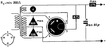
Thanks Emilio, more good advices from You.The question I did not write in the last message is about capacitors in the rectifier stage.So the question is how much microF I can place after the first choke , and how much after the second(how much max.)In the Philips tube vademecum for AX50 is recomended max. 64microF.Is this means that I can put total in the rec. stage 64microF or I can put more after a second choke.Also I want to ask can I put double microF if I use two AX50 in the rectifier.
Thanks , Peter. |
|
Emilio Ciardiello
31.Mar.08 |
13
Dear Peter, when using an inductive input filter, the rectifier does not see the smoothing capacitor: it charges the magnetic circuit of the inductor. For this reason, provided that the inductance of the smoothing choke never falls under the critical value, the current in the rectifier is always limited by the first inductor, regardless of the capacitance value. The maximum capacitance value, given by tube manufacturers, usually refers to capacitive input filters: you cannot exceed this value to avoid excessive current peaks in the rectifier. When using an inductive input filter, you must stay over the critical inductance to have the current limited to a safe value. Since the inductance varies with the current, it is important a well-done choke, a so-called swinging choke fully characterized from the minimum up to the maximum expected current. You should first calculate the inductance minimum value in no signal and in maximum current drain conditions, then the coil winder technician will assign practical values to the iron core winding. Or you might buy a standard swinging-choke from the very few manufacturers left. At this point you may calculate the minimum (not the maximum) value for the capacitance(s) at the wanted output ripple, using the formulae from the pages I mailed directly to you. Nobody can say how many microfarads you need, without the design details of the entire amplifier. The maximum acceptable ripple varies according to the specification you decided, but also depends upon the configuration of the audio power stages. Smoothing capacitors should be large enough even to act as energy reservoir during the loudest prolonged bass notes. All these considerations however just give you the idea of the minimum required capacitance for the given application. There is no upper limit to the capacitance value, but the common sense. The graph from Henney, given above, shows that any increase in the capacitance gives an improvement in the ripple level. In the past, large capacitors were big and expensive; hence designers had to calculate their exact value, as compromise among electrical specifications, volume and price. Today you can find cheap and small snap-in electrolytic capacitors of several hundreds microfarads, made for switching power supplies. So, unless you are planning to use old-fashioned oil-filled paper capacitors in your amplifier, you can simply select a commercial value, even 10 or 20 times greater than the calculated minimum. Remember however that large capacitors at high voltages store a lot of energy and you must slowly discharge them before any attempt to operate inside the amplifier. Emilio |
|
Perica Adnadevic
01.Apr.08 |
14
Dear Emilio, now I can say You provide to me the all necessary data for my "problem".You know,there is no more literature about this old stuff, but there is so much enthusiasm for self made tube amp's.It is very exciting to made something with Your own hands.You can enjoy and conect with so beautiful old times. In the last message You wrote about what capacitors I want to use.I decided to use oil capacitors from 70's(Siemens made).If You have a coment about this please write. There is no words I can write how much I'm greatful to You for helping me about this.Thank You so much again.Sincerely,Peter. |
|
Emilio Ciardiello
03.Apr.08 |
15
Dear Peter, my best wishes for the success of your challenge. If you are looking for a good reference book, with about 1500 pages of useful circuits, tables and tips on audio amplifiers, and other items, you should buy the ‘Radiotron Designer’s Handbook’ by Langford-Smith. It should be easily available, as it was reprinted some years ago; it should also be available on CD. Emilio |
|
Perica Adnadevic
03.Apr.08 |
16
Dear Emilio, thanks for everything.I'll try to find a book You advice to me. I hoppe there it will be more good people like You.The World will be beter. With very best wishes,Peter. |
|
Hans-Dieter Haase † 5.2.18
04.Apr.08 |
17
Look here for t´he book. |
|
Perica Adnadevic
05.Apr.08 |
18
Thank You Hans.I think I will buy this book, it is perfect for my hobby. Peter. |
End of forum contributions about this tube
| Data Compliance | More Information |

