ECH81
|
Variants |
|||||||||||||||||||||||||||||||||||||||||||
|
Hits: 6270 Replies: 1
ECH81Curve traces
|
|
|
Joe Sousa
06.Dec.10 |
1
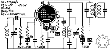
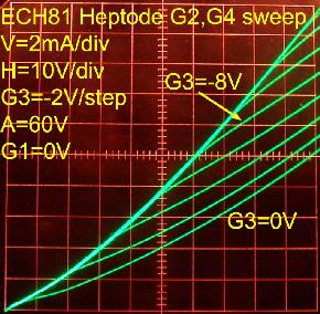
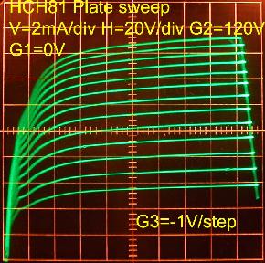
Fellow Radiophiles, In recent discussions with Jacob Roschy, it has become apparent how popular and versatile the ECH81 tube is. Jacob has used it in many of his transmitter and receiver designs. However, the extensive manufacturer's curves focus on the original intended application as Heptode-Mixer&Triode-Oscillator, or as Heptode RF amplifier. I include here some additional curves that explore the behaviour of G3, which is normally used for local oscillator (LO) injection. This choice of grid requires a relatively wide p-p input for efficient mixing, but this is easily supplied by the independent triode oscillator. This leaves G1 independently available for RF input with remote cutoff. The nominal conversion transconductance is specified as 775uS. Other Heptodes, such as the very common 6BE6/EK90, are designed for LO injection at G1 and RF input at G3. In the self-oscillating configuration, the nominal transconductance is 455uS, and up to 600uS with a heavy 1mA separate LO injection into G1. Some of the advantage of the ECH81 is the higher transconductance of RF input grid.
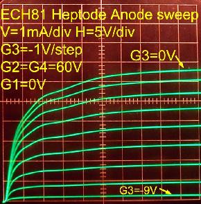
Comparing the effect of the control grid G1 on plate current to the effect of the LO injection grid G3. G2=G4=60V The third photo was taken with 5V/div horizontally.
Comparing the effect of control grid G1 with LO injection grid on G2-G4 Screen currents. Note the non-inverting voltage gain and negative transconductance from G3 to G2-G4.
G2=G4=120V. This is the nominal recommended screen bias. Note how much higher the gm1=<4.6mS is than the gm3=<1mS. This is even more so, near 0V bias for either grid.
The very modest gm3 has hardly any effect when added to gm1 by driving both grids simultaneously as seen in the next photo. The photo on the right was done with -2V/step at G3. Note how sudden and sharp it's cutoff is with -18V at the lowest trace.
The following curves were done with reduced G2=G4=30V screen voltage with particular application to the little Luis Freixa Periquito radio I repaired recently. Each column of the following 9 plots represents three source resistances driving the stepped grids: 0Ω, 100kΩ, 1Meg0Ω. The first row shows the control of G1, the second row shows the control of G3 and the last row shows the simultaneous control of G1+G3 in parallel drive. Note how severe the attenuation is at low control grid G1 voltages at 0V. The third grid G3 retains a high impedance down to zero volts as can be seen in the right-most column. As was seen for higher voltages at G2=G4=120V, driving G1 and G3 simultaneously, as opposed to driving just G1, has little effect on the plate current with G2=G4=30V. Regards, -Joe |
|
Bob Isaac
08.Dec.10 |
2
Joe, If ever I am having doubts about my lack of knowledge in the area of radio, I simply read one of your articles. Your brain is a scary thing indeed. All joking aside, thank you for yet another informative and interesting article. Please 'keep em coming!' Thanks again, Bob |
|
Hits: 6582 Replies: 0
ECH81 (ECH81) mit Gas: Auswirkung auf Schwingkreis
|
|
|
Dietmar Rudolph † 6.1.22
20.Jun.08 |
1
Die Auswirkung des Fehlers Bei der Siemens Kammermusik-Schatulle M57 (Vorstufensuper für LMK) war der AM Empfang sehr schwach. Es fehlten ungefähr 40 dB Verstärkung. Das Magische Auge (EM80) sprach auch beim Empfang des Ortssenders (Deutschlandradio Kultur, 990 KHz) praktisch nicht an; es war nur ein grüner Strich in der Mitte zu sehen. Die ECH81 arbeitete jedoch augenscheinlich als Mischer korrekt. Dagegen war der Empfang auf UKW gut und das Magische Auge schlug voll aus. Das H-System der ECH81 funktionierte als 2. ZF-Verstärkerstufe (10,7 MHz) anscheinend richtig. Suche nach der Ursache Aufgrund der Auswirkung (UKW: gut; LMK: schlecht) fiel der Verdacht zunächst auf das Tastenaggregat. Die ursprünglich versilberten Kontakte sind mittlerweile ziemlich schwarz. Vielleicht hat der Vorbesitzer nur noch UKW gehört und die AM-Kontakte sind deshalb mit einer schlecht leitenden Schicht überzogen? Eine Behandlung der Kontakte mit "Kontakt 61" und häufigem Schalten brachte jedoch keine Verbesserung zustande. Nächste Überprüfung war der Widerstand der Schaltkontakte mit dem Ohmmeter. Auch die AM-Kontakte hatten kleine Übergangswiderstände. Was nun? Nun hat die Schatulle M57 eine Besonderheit, nämlich 3 Tasten für die Mittelwelle: MW (für Außenantenne), MW (für Ferritantenne) und MW (für Ortssender-Empfang). Schaltungsmäßig ist der AM Teil hierbei so realisiert:
Also, Radio wieder einschalten und Eingangskreise wobbeln. Durchlaßkurve sieht zwar wieder vernünftig aus, aber wieder fehlen ca. 40 dB Verstärkung. Drehen wir uns im Kreise?? Also Trimmer des Zwischenkreises verdrehen: Keine Wirkung erkennbar! Kern verdrehen: auch keine Wirkung! Die sichtbare Resonanzüberhöhung kommt vom Vorkreis, wie sich durch Verdrehen des zugehörigen Trimmers feststellen läßt. Also ist der Zwischenkreis völlig "platt"!? Da jedoch die Messung bei ausgeschaltetem Gerät ergab, daß der Zwischenkreis eine Resonanz zeigte, kann es nur noch an den beiden Röhren (EF89 oder ECH81) liegen. Messung der ECH81 mit dem Röhrenprüfer Die Überprüfung auf dem Funke W19 ergab:
Eine neue ECH81 und ein nun fälliger Abgleich der Eingangskreise brachte das gewünschte Ergebnis. Das Ausgangskennlinienfeld der Heptode der ECH81 Die besagte ECH81 hat zusätzlich die Besonderheit, daß der Getterspiegel bis zu den Pins heruntergeht, wie die beiden Bilder zeigen.   Interessant ist die Messung der Ausgangskennlinien der ECH81, wobei die Kennlinien ohne und mit einem Widerstand (100KΩ) in der Gitter-1-Leitung aufgenommen wurden.   Das rechte Kennlinienfeld ergibt sich, wenn ein Widerstand von 100 KΩ vor dem Gitter 1 liegt. Dies ist ähnlich dem Betriebsfall im AM-Bereich, wobei beim M57 tatsächlich ein noch größerer Widerstand (ca. 3 MΩ) vor dem Gitter 1 liegt. Hier sieht man, daß die Kennlinien ansteigen, wie man es sonst nur von einer Triode her so ähnlich kennt. Aber - die ECH81 hat trotzdem in den AM-Bereichen als Mischer gearbeitet, obwohl sie den Zwischenkreis infolge Gitterstromes so gedämpft hat, daß dieser keinerlei Resonanzüberhöhung mehr hatte und demzufolge die Verstärkung im AM-Bereich viel zu gering wurde. Die gleichen Messungen mit einer "gesunden" ECH81 ergaben kaum meßbare Unterschiede zwischen beiden Kennlinienfeldern. MfG DR |
|
Hits: 10088 Replies: 1
ECH81 (ECH81)
|
|
|
Pietro Gallia
10.Aug.06 |
1
I have some ECH81S (Telefunken), but I don't know the difference with ECH81. |
|
Ernst Erb
10.Aug.06 |
2
Dear Pietro Since you wrote in English - well done for being understood by more members - you should show the flag for English. Many members will probably have opted out articles with some other language flags - or they will not open languages they don't understand. If you want that your question is seen by more members please go to this thread, click "Edit", change language to English and then click Submit - and your question will have the flag for English. The right language selection at the Wysiwyg-Editor is only necessary for the first post of a thread since this one shows the language flag for the whole thread. cordially, Ernest |
End of forum contributions about this tube
| Data Compliance | More Information |

