PM12A_UX
|
|
|||||||||||||||||||||||||||||||
|
Entradas: 800 Réplicas: 4
Wrong pin connections.
|
|
|
Stuart Irwin
25.Jul.23 |
1
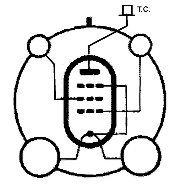
Hello. I have noticed that with this valve the pin connection diagram shown is incorrect. Pin 2 is the screen grid and the top cap is the anode. Regards, Stuart Irwin |
|
Harald Giese
25.Jul.23 |
2
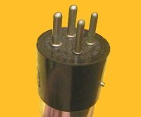
Hi Stuart, is this the correct pin assignment of the PM12A_UX? Does the tube have a bajonet guide pin as shown in the picture? Is the filament center tap connected to the suppressor grid, as shown in the picture? If yes, I will replace the presently shown pin assignment picture by this one.
Best regards, Harald |
|
Wolfgang Holtmann
25.Jul.23 |
3
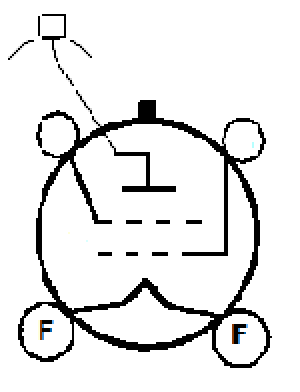
Hello together I just uploaded the corrected base diagram;
Kind regards P.S. |
|
Harald Giese
25.Jul.23 |
4
Hi all, Wolfgang's pin assignment picture has now been activated on the PM12A_UX page. Regards, Harald |
|
Stuart Irwin
26.Jul.23 |
5
Hello Harald. In answer to your questions: That diagram is correct except that there is no suppressor grid. The valve, from an example I have, does have a bayonette pin. Regards, Stuart
|
Fin de las contribuciones al foro de válvula
| Cumplimiento de datos | Más información |


