SN-856-F
|
|
|||||||||||||||||||||||||||||
|
Hits: 5578 Replies: 1
SN-856-F (SN-856-F)
|
|
|
Joe Sousa
16.Sep.09 |
1
Hello Radiophiles, A recent thread started by Javier Albinarrate about very small subminiature tubes resulted in the identification of the Sylvania SN-856-F prototype thyratron tube. Tube expert Ludwell Sibley kindly provided me with 5 samples and information about the origin of this very small 17mm long tube. There was no available data for the tube, so I set about taking some measurements on one of the 5 samples. First off, it was necessary to estimate the filament voltage for the tube. The cold filament resistance is 3 Ohms. A very fine coated filament of this type generally has a 4 fold increase in resistance at running temperature. A sweep of filament Voltages in 100mV to 200mV steps soon showed that 1V produced a drain of 86mA, which represents the four fold increase in filament resistance, to 12 Ohms. This method of estimation of filament temperature relies on using the tungsten of the filament as a temperature indicator. Tubes with a similar cathode/filament construction, and a similar coating, run at similar temperatures. Service up to 20mA at the Anode seems reasonable with a filamentary cathode heating current of 86mA. The Anode fires around 20V when the grid voltage is zero, or a few uA of current is supplied through a current limiting resistor from a positive source. More grid current than needed to fire the anode tends to steal Anode current. The anode drop for the sample shown in the curve tracings was around 20V, but it was closer to 10V for the other samples. An open Grid behaved similarly to a grounded grid, with the anode trigger around 20V. A mere -3.5V of negative grid bias was enough to hold off firing at the Anode up to +200V. The Anode firing voltage is about -57 times the grid voltage. For example, a +57V Anode firing voltage is obtained with a -1V of grid bias. These measurements were taken on a Tektronix 575 Transistor Curve Tracer. The first two photos show Anode I/V characteristic curves. The first photo was taken with a sequence of negative grid voltages, and the second photo with a finer Anode voltage scale was taken with positive voltage steps through a current limiting 2K2 resistor.
I drew a white line through the tips of the anode trigger points to show the linear relation between anode trigger voltage and negative Control grid voltage. The slope is -57AnodeVolts/GridVolt This slope is akin to mu in a vacuum triode. This thyratron is quite sensitive, in that it does not take much voltage to hold it off.
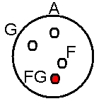
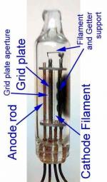
Now a few closeup photos. The photos were taken with a Logitech QuickCam Pro with 2megapixels of resolution. The macro capabilities are quite good for photographing tube details. The minimum focus distance is 2 inches. The Plasma is Purple, instead of blue, suggesting He and/or Ar gas. The rounded grid plate is supported on two rods: The wire lead pinout is oriented by a red dot of ink in the filament wire that is tied to the getter plate: The construction sequence is comprised of 4 elements: 1- A getter plate with three dimples. This plate also serves as the connection for the far end of the filament with an additional very small spring connecting this getter plate to the top of the filament. 2- The filament has a single run and runs in front of the dimpled getter plate. 3- The rounded grid plate with a small aperture at the center blocks the full extent of the cathode. The rounded grid plate is supported by two longitudinal rods. 4- The anode rod sits behind the rounded grid plate and is aligned with the grid plate aperture. The Grid plate aperture now seems like an obvious feature of a gas tube. Somehow, we were hoping for some sort of linear triode, perhaps of the Gammatron/gridless-Audion variety.
Ludwell Sibley has agreed with the possibility that "Doc" Edgerton of MIT, and of "flash stop-motion photography" fame, may have been involved in the design these tubes for Sylvania. Our own tube administrator Roy Johnson has suggested that these tubes might have been developed as triggering devices in proximity fuses to trigger the bomb fuses that were carried by missiles. Thank you Ludwell Sibley, for providing the free samples and priceless identification information. Regards, -Joe |
|
Robert Sarbell † 22.3.22
18.Sep.09 |
2
Hello Joe and Roy, I respectfully suggest that the small tubes researched by Joe are quite probably some of those which were developed and produced through combined efforts by the British and US defense ministeries during the early 1940s. . . .
To be most impartial to the accurate presentation of my information, I also state that the developmental and production efforts toward the VT (variable time) fuze technologies, were aided by the efforts of a specific crew of professors and scientists at the University of Toronto working under the auspices of Dr C J McKenzie in coordination with the National Research Council in Ottawa. This information was presented in a 3-page, illustrated article from the INCO Triangle (a trade journal) in February 1946; entitled “Radio Tubes Shot through a Gun”.
I agree completely with Roy about the very small vacuum tubes produced by several manufacturers - including the Crosley manufacturing (in Cincinnati, Ohio) and Hygrade Sylvania production facilities (in Emporium, Pennsylvania) and RCA in the early 1940s. . . . . . I have attached the 2 pages which describe the T3 tubes - as they were described and photographed in the Sylvania News Technical Section Volume II - specifically the issue dated November, 1945. NOTE: Please keep in mind that the very specific electrical and performance details of these small tubes were obviously still classified at that time. . .some details were de-classified as early as 1960 and full de-classification was effected in 1976. The US military designation of these Proximity fuzes ranged from the Mk 32 up up to Mk60 - the Mk56 series were produced for use in the British Navy 5" naval guns Attachments
|
|
Hits: 3195 Replies: 4
Did these tubes ever reach production?
|
|
|
Javier Albinarrate
07.Sep.09 |
1
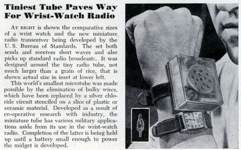
Hi, surfing the net I found and saved this (I don't even recall where). Does anyone know if these tiny tubes ever reached production or if they were standardized?
Regards!
Javier Albinarrate
|
|
Joe Sousa
09.Sep.09 |
2
Hello Javier, I sent the info in this thread to tube expert/historian Ludwell Sibley, and he identified it in this response to my email: [snip] If they're talking about a submin tube, four leads, body 17 mm long, with a Lud offered to give me a sample, once he finds it. I will then photograph it, measure it and post the results. The OTB is the Old Timer's Bulletin, which changed name to the Antique Wireless Assocination Journal. Regards, -Joe |
|
Javier Albinarrate
09.Sep.09 |
3
That is really amazing! As I assumed that these never reached commercial production, it seemed obvious that they faded in the midst of time... but instead, not only somebody clearly identifies them.. but he has samples too! Thanks for the enquiries Joe! |
|
Joe Sousa
16.Sep.09 |
4
Hello Javier, The tube that Ludwell identified is actually a gas Thyratron. So it could not have been used for linear amplification. See details at SN-856-F Regards, -Joe |
|
Javier Albinarrate
16.Sep.09 |
5
Hi Joe, What an amazing and detailed job! Yep, certainly any tiny thyratron use has really huge chances of being involved with bomb fuses or missile development, but that would mean that the technology was there, and that the need for other tubes was there too. Unfortunately I doubt that such a lucky strike like this one (finding samples) can take place twice. Regards! Javier |
End of forum contributions about this tube
| Data Compliance | More Information |


