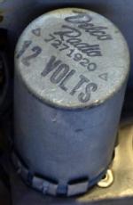
Vibrator
|
|
|||||||||||||||||||||||||
|
Visite: 1331 Risposte: 0
Vibrator Pack
|
|
|
Michael Watterson
29.Sep.17 |
1
The Vibrator is essentially a mechanical implementation of a Forward Switch Mode Power Supply. They first appear in the 1930s and are used into the 1950s when a pair Germanium Transistors replaces the the mechanical contacts. The Transistor versions are still occasionally seen. A CFL electronic ballast is a variation of the transistor version. The DC power supply option on the Yaesu FT101 series radios uses a pair of transistors with feedback from the mains transformer to replace the contacts. The mechanical contacts and coil are quite simiar to a relay wired to self oscillate at the mechanical resonant frequency of the contact arms. The purpose is to generate between 90V to 600V HT for valve (tube) Anode/Screen power supply from a battery power supply often used directly for the filaments/heaters. The "pack" contains as a minimum a change over contact between two stationary contacts. The energising coil is disconnected when the centre contact, the "reed" moves from the normally closed contact. This causes the reed to fall back. The natural mechanical vibration frequency of the reed contact can be between 40 Hz and 400Hz. A 100Hz approximate rate is common.
Shunt or Series Reed Energizing coilThe coil can be across the supply (usually a 6V, 12V or 24V Lead Acid battery) or in series with the supply and load. The immediate load is a centre tapped transformer primary. Each half of the winding is thus in turn connected to the supply causing a reversal in DC magnetisation through the core. The transformer can thus be similar construction to laminated soft iron / Silicon steel used for AC mains or Audio. If the frequency is higher then the size can be smaller for the same power. A Series coil will vary in frequency with load and may be erratic at very low load currents. A Parallel or Shunt coil takes a fixed amount of power and gives a steady speed, but is still influenced by supply variation.
Types of Vibrator pack.
SnubberThe switching off of current is abrupt which with no load and an ideal coil on the transformer would give an infinite voltage. In practice the contacts would arc and the output would have massive switching spikes. A "snubber" is needed to "tune" the system. This can be a capacitor or a capacitor with a series resistor. across the primary OR the secondary. Increasing the capacitor will dampen the switching too much and too low will cause spikes and arcing, so a replacement must be the correct value within 10%. The voltage rating must be very high as the regular AC on Secondary is twice the DC voltage. In practice 1500V rating would be likely for a 200V DC secondary. The secondary is preferable to primary as it helps filter noise on the HT.
Supply and SocketThe pack can have 4, 5, 6 or 7 pins. Usually a UX type base. Some 6 pin synchronous units on car radios are designed to be inserted at 180 degrees in the socket if the Radio is changed from +ve Earth to -ve Earth or vice versa. Non-Synchronous versions can use any polarity of supply. Reversing supply Polarity on #3 or #4 will reverse the HT polarity! Reversal of supply on a Transistor based "Vibrator" pack may result in failure (PNP) or a short (MOSFETS have inherent diodes on Source / Drain).
Operational issuesCommon types used in UK/USA/Australian Models are Oak and Plessey. If disused a long time it may not start due to tarnish on the contacts. One solution is to unplug and holding in one hand slap hard with the other several times. Then reconnect the power and with valves unplugged and suitable dummy HT load, toggle the supply on and off (7V for 6V, 14V for 12V and 28V for 24V). If the Vibrator is good then approximate minimum startup voltages are (Recommended Non-Gel Maintenance free Lead acid operational range): 6V @ 4V (5.4 to 7.1) 12V @ 8V (10.8 to 14.2) 24V @ 16V (21.5 to 28.5) Gel type cells don't have as high an end-point but are more easily damaged by over discharge. Traditional Wet Lead acid that need regularly topped up have slightly higher trickle charge levels than Gel but less than maintenance free types of 6.9, 13.8 & 27.6V. |
Fine delle discussioni nel forum su questo valvole
| Conformità dei dati | Ulteriori informazioni |

