grundig: Circuitry Analysis
grundig: Circuitry Analysis

1. Anyone may ask questions, and we encourage you to do so.
2. Answers should only be given by those who are certain of their answers; please avoid conjectures.
To thank the Author because you find the post helpful or well done.
(Translation of text originally by Thomas Günzel)
To get started, here are my first two questions regarding the FM tuner:
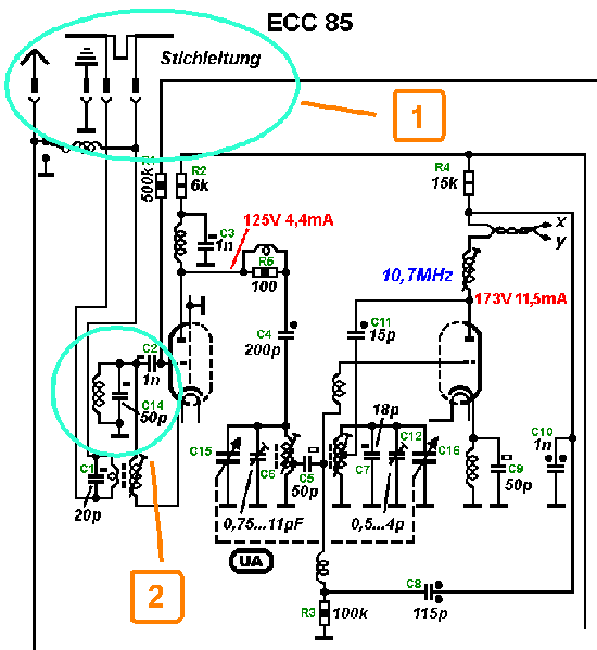
1. What is the tuning stub at the input of the FM tuner for?
2. What is the purpose of the resonant circuit with C14 on the grid of the first triode section of the ECC85?
To thank the Author because you find the post helpful or well done.
(Translation of text originally by Götz Linss)
Here's my attempt to answer the first question:
In my 4040W/3D there is a simple wire dipole built into the cabinet as an FM antenna. As a dipole, it has a theoretical center-fed impedance of 75 ohms. In addition, for the wavelength of the FM band, the dipole is too short. The tuning stub (or "matching stub") is necessary to match the antenna to the 300 ohm twin lead that goes to the tuner input.
Götz Linß
To thank the Author because you find the post helpful or well done.
The first answer
(Translation of text originally by Hans M. Knoll)
Hello Herr Linss,
That's almost entirely correct. What's missing is the answer of what a tuning stub is and why they were only used for a time? What replaced them?
In addition, how did the impedance transformation from 75 to 300 ohms work?
Once we get started, we'll see what comes next.
Later, I'll provide my explanation. This shouldn't be a monolog.
HMK
To thank the Author because you find the post helpful or well done.
Tuning stub
(Translation of text originally by Thomas Günzel)
Hello Hans,
What impedance does this ominous tuning stub have? The tuning stub is shorted. How long is it?
Thomas
P.S.: Can another member who has this radio take a picture of this tuning stub?
To thank the Author because you find the post helpful or well done.
Z = ?
(Translation of text originally by Hans M. Knoll)
Thomas,
Parallel wire conductors are used for impedance transformation or as a reactance.
In many configurations, the dipole is connected to one end of the tuning stub, and the lead in is connected somewhere along the line. Then it functions as an impedance transformer.
If the end of the stub is either open or shorted, then the impedance at various points along the line is different (depending on frequency).
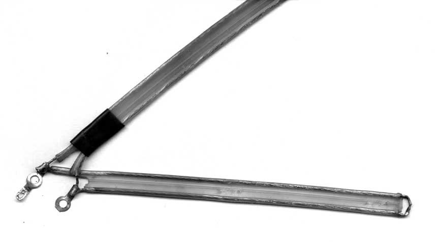
In the previous case and for the dipole antenna use here, this line is shorted at the end and shorter than a quarter wavelength (about 100 mm long). It therefore functions as an inductance, with very low loss. Thick, sliver plated wire is used.
HMK
In the attached picture, the voltage (solid line) and the current (dotted line) are shown over the length of the line.
.png)
At the terminals, the impedance is the ratio of the two.
Matching stubs and parallel transmission lines (another thread in German on this subject)
To thank the Author because you find the post helpful or well done.
Impedance transformation with tuning stub
(Translation of text originally by Thomas Günzel)
Hello Hans,
Thanks for the competent answer!
Tuning stubs are normally very narrow band -- naturally it depends on the losses.
Does this tuning stub cover the whole FM band uniformly?
Thomas
To thank the Author because you find the post helpful or well done.
(Translation of text originally by Hans M. Knoll)
Since it serves as an inductance, it goes linear with omega (frequency) up to a quarter wavelength (mistake corrected).
.png)
It's just part of the antenna. It is only broad band up to a point. To cover a bigger frequency range, the length of the stub would have to be adjusted.
During development, a tuning stub with some excess length was used, and a sliding short-circuit contact was used to determine the correct length.
The bandwidth depends mainly on the antenna. At various times, wide aluminum foil strips were used for the antenna.
Later I'll show an antenna here. Here is the principle:

Section "a" is the tuning stub in our case. The diagram doesn't exactly match our case, however. Section "b" is the whole length of the stub in the radio. In the 1960's, there were lengths of line strung back and forth on the back cover, which were also used for impedance transformation.
HMK
Attachments:
Shorted_stub (9 kB)
Dipole (8 kB)
To thank the Author because you find the post helpful or well done.
Picture from 5040 W (without -3D suffix)
(Translation of text originally by Hans M. Knoll, including edits)
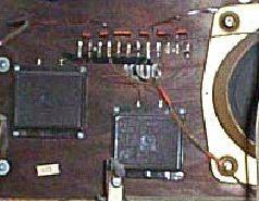
Herr Amend sent me a picture. It's from a preceding model.
Instead of using a tuning stub (which has already been explained to function like an inductor), a coil is used. Almost every company did it this way.
Here is a picture from the 5040W (without -3D suffix) with a coil:

Telefunken had thick wires and big coils. If they got squashed, the inductance was no longer correct. With a tuning stub, only the length matters.
Since tuning stubs were expensive, they were later replaced again with coils.
There was an inquiry about this: The stub, as it is shown here, is cut twin lead, stripped and soldered by hand. The coil was made by automatic equipment, the same way springs are wound.
Herr E. Kull has provided a picture of one particular matching stub. The length is 14.5 cm. Thanks!
To thank the Author because you find the post helpful or well done.
Request
(Translation of text originally by Thomas Günzel)
Dear members,
Who has a 5040W/3D and can take a picture of this tuning stub?
It would be great for ongoing documentation!
Greetings,
Thomas
To thank the Author because you find the post helpful or well done.
IF trap
(Translation of text originally by Georg Beckmann)
I'll try to explain the resonant circuit. Perhaps it is a circuit that works at the IF frequency of 10.7 MHz. With this circuit (grounded grid triode amplifier), the cathode is the input. At all frequencies other than the IF, the grid is loaded. At the IF frequency, the circuit is resonant and therefore high impedance; that is, the amplification of the stage is reduced.
In case I don't have it right, I'd be happy of Herr Knoll would set things straight. (I'd be even happier if he said I was right!)
Greetings,
Georg Beckmann
To thank the Author because you find the post helpful or well done.
(Translation of text originally by Andreas Steinmetz)
Dear colleagues,
This is really fun!
At the moment I'm not quite sure, whether we're finished with Question 1. If so, then I would like to post something on Question 2. In case Question 2 isn't up yet, I don't mind if my post gets deleted. First we've got to figure out how we're supposed to behave in this thread.
On Question 2:
The resonant circuit with C14 has a pretty high capacitance of 50 pF, so it can really only be tuned to the FM-IF frequency. That means it's a short circuit at DC and HF, and the first triode of the ECC85 is used in a grounded grid manner. The resonant circuit in question prevents unwanted IF signal from going backewards to the antenna through the input transformer and being radiated. We assume that via parasitic capacitance there is some IF voltage on the cathode of the first triode of the ECC85. Then it indeed reaches the secondary winding of the input transformer, but then the function of the high impedance IF trap comes into play. Therefore the circuit isn't closed and no current flows, and as a result, there actually isn't any inductively coupled signal on the antenna side of the input transformer.
Andreas
P.S.: In case I'm wrong, please correct it or delete the post!
To thank the Author because you find the post helpful or well done.
Radiation
(Translation of text originally by Georg Beckmann)
Hello Herr Steinmetz,
We posted at the same time, but I think you're right -- perhaps both of us are.
Greetings,
Georg Beckmann
To thank the Author because you find the post helpful or well done.
What and when?
(Translation of text originally by Hans M. Knoll)
Since this is new territory, it will take a while until everything is running smoothly.
Herr Guenzel, as the initiator, can untie the knot and set the tempo...
Herr Steinmetz and Herr Beckman, the "coil" is just a choke to allow the anode current to flow. That's just a tidbit of more discussion yet to come. :-)
Radiation from the oscillator is sometimes good. Although, in the back of my mind from 1954, I think it took me two days before I believed it...
Tomorrow I'll show my cards.
HMK
To thank the Author because you find the post helpful or well done.
(Translation of text originally by Andreas Steinmetz)
Aha, Herr Knoll!
If that's just a choke, then it isn't tuned to 10.7 MHz. But then this should not have discussed as a resonant circuit. Then we also have to dismiss the concept of grounded grid operation as well. Then we'll be discussing bridge circuitry, which has the purpose of suppressing radiation of, for example, signal from the oscillator, or to fight any tendency for the stage to oscillate. It's getting exciting, and I like this!
Regarding the way this thread is getting started -- I didn't want to pose any conjectures. But unfortunately my first assumption turned out to be wrong, and therefore the conclusion didn't hold either. Perhaps the moderator should provide some more precise instructions, so this doesn't happen very often...
Let me repeat: This thread is a great idea!
Andreas
To thank the Author because you find the post helpful or well done.
Stupid question!
(Translation of text originally by Thomas Günzel)
Hello Herr Steinmetz,
I intentionally asked these questions, because I myself -- as an engineer with a degree in microwave technology -- don't know what the purpose of these circuit elements was! Since I made this mistake, others who don't feel confident enough to ask questions should not be bashful!
Sometimes even "experts" end up on slippery ice!
Let me repeat: This shouldn't be just for experts; it should also be a Q&A forum for "laypeople."
A recap of the bold excerpt from Post 1:
1. Anyone may ask questions, and we encourage you to do so.
2. Answers should only be given by those who are certain of their answers; please avoid conjectures.
We do not want endless discussion about “what if?” or “but…” or “perhaps…”
So, have fun with this thread, which is certain to be a long one.
Thomas
P.S.: We're all eager to hear the answer from Hans! :-)
To thank the Author because you find the post helpful or well done.
5040W3D - Photo of FM stub

I attach a photo of my 5040W3D with the short FM stub, as stated by Herr Knoll - it measures at nearly 119mm from closed end up to the copper wires of the dipole.
For possible dating purposes the large oval speaker reflects date of 23 Okt 54; and chassis reflects 444 14637.
Respectfully,
Robert Sarbell Attachments:
- 5040W3D FM ant stub (114 KB)
To thank the Author because you find the post helpful or well done.
Component values in the resonant circuit
(Translation of text originally by Karl-Heinz Bradtmöller)
Hello,
On Question 1:
Here's a little example: my WU1052 has a built-in dipole like the one mentioned in Post 8 with the silver plated coil for matching. With it, a bridged external longwire antenna won't overload the FM input with an AM signal due to asymmetry. The AM signal is effectively shorted by the coil, meaning that it applies to both halves of the FM dipole as a common mode signal that gets eliminated by the differential FM input.
On Question 2:
To me, the resonant circuit is "bandpass" component to improve the rejection of out-of-band signals. It bugs me that it would be referred to as a "trap", because these are "usually" built as series resonant circuits. As an example I refer to the schematic of the "Ehrenfels," in which these components are missing, even though the rest of the schematic is very similar. Therefore these components can be left out. It depends on the sizing of the inductance, which would indeed be small, so that a bigger value for C would be used.
Best regards,
K.-H. B.
To thank the Author because you find the post helpful or well done.
A hint from Herr Knoll
(Translation of text originally by Georg Beckmann)
Hello Herr Knoll, Herr Steinmetz, and Forum,
Let me take a crack at the solution. Many radio diagrams are drawn in such a way (perhaps even intentionally), so that the function is not immediately understood.
The hint from Herr Knoll, that the coil in parallel with C14 is just an HF choke, to provide a DC load for the cathode, completely changes the picture. (see sketch in attachment below)
Therefore this is my assertion: L1, L2, along with Ca and C14 form a type of bandpass filter for the FM tuner input. At the junction of C14 and L2 there is a series resonance; that is, a high voltage, with little current to or from the grid.
At resonance, a larger current flows through L2 via the cathode, since the cathode input is low impedance.
Any HF signal that gets coupled via parastic capacitance in the triode in the reverse case only results in a small current, with the result that very little of this interference gets applied to the antenna.
Attachment:
6400000209 (42kB)
To thank the Author because you find the post helpful or well done.
(Translation of text originally by Hans M. Knoll)
On Question 2:
As already observed, the question wasn't 100% properly worded. It is in fact not a resonant circuit.
If the person who asked the question -- in this case Thomas -- had been clear, then he would have already answered it for the most part.
But it's almost always the same problem that the impression one gets from the diagram seldom reveals the function. That's the direction Thomas was headed in.
If it's already difficult enough with the original diagrams from the manufacturer, then it's also not simple to grasp the meaning on the professionally copied version by Lange-Nowich and Lange, even though they are technically experienced. This particular point is impossible to see with L&N. See this: www.radiomuseum.org/protect-path.cfm
Who will venture to provide an explanation?
You have to check to see whether the answer is already given in the question.
It is also often said that these components are not to be found in later models... However, that does not mean the components had no benefit, and also doesn't explain what they were for.
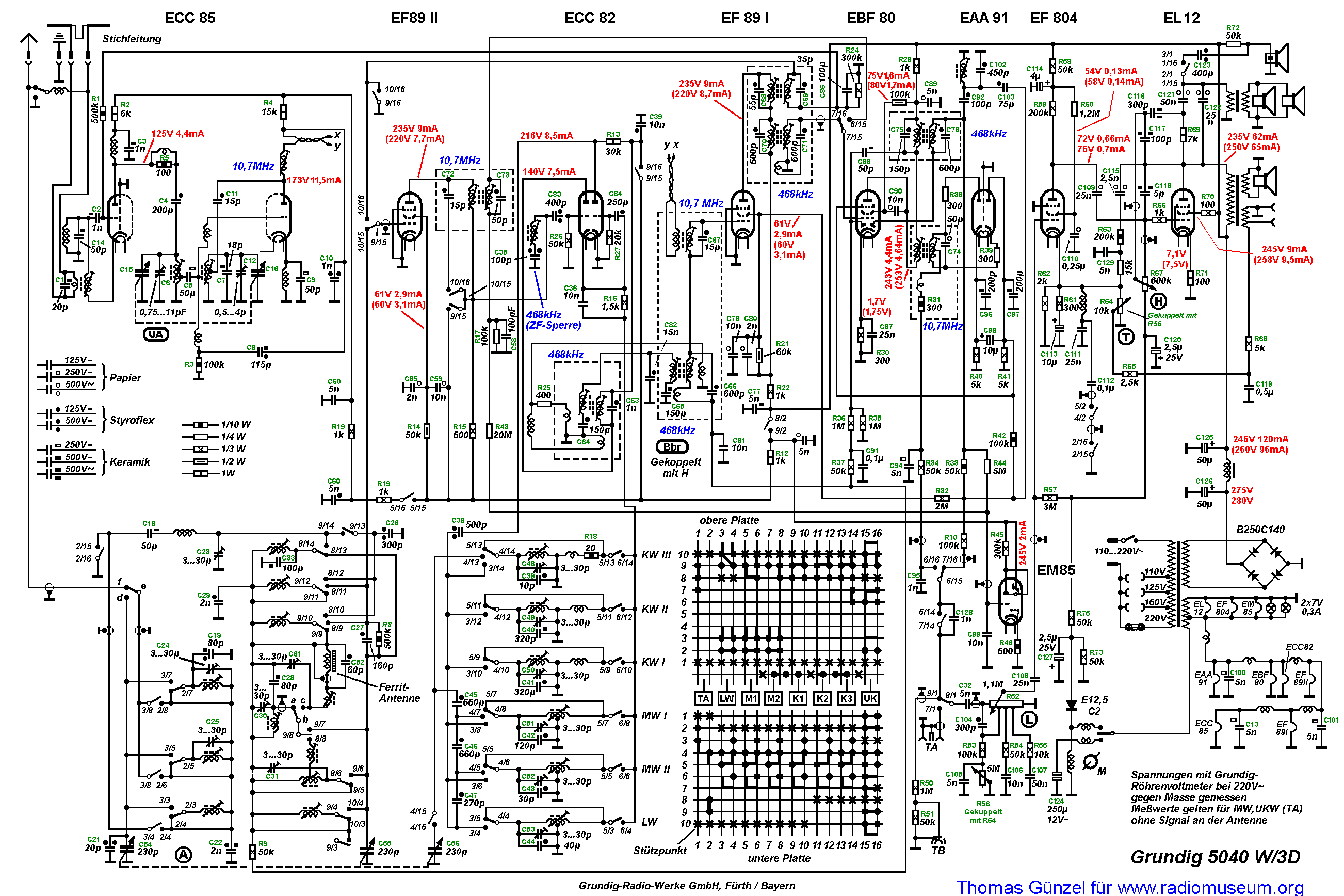
The background for this version in the 5040W/3D: The preceding model 5040W had a circuit in the FM input stage with three triodes that functioned as cascodes and an additive mixer. This was a top-notch technology that was found later only in SABA, Siemens, Nogoton and FS sets. The use of the newer ECC85 isn't necessarily an advance. Everything that was technically possible had to be squeezed out of this tube.
With that introduction, we arrive at our subject. Squeezing everything possible out of the tube means that everything gets pushed to the limit. Circuit quality, resonance resistance (L/C ratio) and the transconductance of the tube. Otherwise the previous stage would need to have provision for an adjustment. When an amplification stage is accessible from outside, it is not entirely simple to keep the stage stable and free of oscillation, because you never know just what someone might attach to the antenna terminals.
Briefly stated, the stage must have full performance without going into oscillation, and must not require any adjustment. To make this work, it is not sufficient to use the published information about a grounded grid circuit. Having the grid grounded doesn't solve all the problems. There is still some anode-to-cathode capacitance, and some feedback from the anode to the input (the cathode), which a broad band resonant circuit between the antenna and the tube removes.
To make sure everything normally works as expected, it is imperative to also neutralize a grounded grid stage.
To accomplish this, there are two versions. One from the Telefunken Tube Applications Manual and the one in the GRUNDIG mixer section. Here is the one from Telefunken. By showing this, I'm only trying to show that a grounded grid stage either can or must be neutralized.

And here's the one from GRUNDIG:

In the diagram, the cathode-grid capacitance is not shown, which plays a role in the function of the circuit, and also the cathode-filament capacitance. In the Telefunken diagram, that is included and assumed. I did not want to ruin the comparison by showing more than necessary in the Grundig diagram.
The cathode-filament capacitance forms a bridge, with the C neutralization on one side and the other with Ca-k and Ca-g, in which the tube sits on teh diagonal. If the bridge is balanced, then the influence of the anode on the input is "neutralized" and quasi-eliminated.
Since there is a phase difference of 180° between the cathode and grid (three point circuit), the grid sees a 180° shifted phase compared to the cathode, and this is genuine neutralization. It was best explained by Herr Holtmann in his Ultra_Audion, where there is a 0 / 180° phase jump. That makes it certain.
The inductance in parallel with the neutralization C only conducts the DC from the cathode away.
With that, I think Question 2 has been answered.
To thank the Author because you find the post helpful or well done.
Short FM-Stub

Thank you very much for the picture.
I will move a copy to the German thread.
Best regards
Thomas Günzel
To thank the Author because you find the post helpful or well done.

Yawn?
What do you want to express with "yawn"?
I'm not familiar with this phrase.
Kind regards
Thomas Günzel
To thank the Author because you find the post helpful or well done.
Super!
(Translation of text originally by Thomas Günzel)
Hello Hans!
... Your answer to Question 2 was outstanding!
It's really phenomenal, how much "know how" the boys from that time had and what tricks they used to meet the requirements.
It's great that you can pass along this knowledge to us.
Regarding the choke, how much inductance does it have?
I'd like to correct the schematic diagram with respect to this, so that no one else gets led down the wrong path by it.
Andreas Steinmetz has already also found a mistake in the schematic, and I'll correct it accordingly.
This schematic should be a living document!
Now, on to the third question:

What is the purpose of R5 in parallel with the coil?
To thank the Author because you find the post helpful or well done.
To thank the Author because you find the post helpful or well done.
On Question 3
(Translation of text originally by Andreas Steinmetz)
Dear colleagues,
This time I'm pretty sure. Nonetheless, I'd be happy to learn more:
Unfortunately high frequency circuits often have a tendency to oscillate at frequencies which are usually well above the working frequency range. These very high frequency oscillations are often caused by small parasitic lead inductances and parasitic capacitances between the wiring, components, and tubes. The coil/choke in question suppresses the tendency to oscillate by limiting the bandwidth from above and separating from one another the components that might oscillate. To prevent the coil from becoming part of a new unwanted resonant circuit, a choke is used which is made in a manner that gives it low capacitance, and it is strongly damped with R5. All this is consistent with the coil being a choke.
This arrangement is often found in TV VHF tuners. There it often has the revealing label "UHF trap."
Andreas
To thank the Author because you find the post helpful or well done.
Matching stub in 5040W/3D
(Translation of text by Thomas Günzel, in which he shows Robert Sarbell's picture from this thread)
Mr. Robert Sarbell put another photo of the matching stub from this set that I would like to submit here.

The stub is, as Hans already said, 119 mm long. The loudspeaker is dated 11/23/1954 and the chassis has the number 444 14637.
Thank you, Mr. Sarbell!
Thomas Günzel
To thank the Author because you find the post helpful or well done.
A side note that applies here
(Translation of text originally by Hans M. Knoll)
Hello Forum,
Herr Linss already mentioned that the 4040W/3D had a wire antenna.
In the picture from Herr Amend we see that the 5040W had a pretty antenna with wide aluminum strips.
Robert has now shown the 5040W/3D which has a wire antenna. How is this an advance?
The advance lies in the 3D arrangement with the side loudspeakers. The 3D was introduced "overnight," and the result -- the FM antenna was no more.
The enormous capacitive loading of the "hot" ends of the dipole by the loudspeakers and their associated wiring made the antenna unworkable. An even worse choice would have been to push the speakers back to the rear cover, but that would only have left enough room for a narrow antenna.
Once it was learned, to connect the loudspeakers nearly 100% of the time through VHF chokes, then it was once again possible to build in broad band FM antennas with wide strips.
Everything went step-by-step. Clever people have already noticed that Grundig mounted many chokes on the sound board (speaker panel).

That's my side note.
HMK
To thank the Author because you find the post helpful or well done.
The metallic trim pieces are also antennas!?
(Translation of text originally by Jochen Amend)
Dear Forum,
What often occurs to me is that the brass trim pieces likewise belong to the antenna system. See the green wire on the right side of the picture, which naturally is also found on the left side of the set.

Best greetings,
Jochen
To thank the Author because you find the post helpful or well done.
Update of the Schematic
An update of the schematic is now available.
Grundig 5040W/3D _ update
You can download it unlimited, no UACS-points will be charged!
Best regards
Thomas
To thank the Author because you find the post helpful or well done.
A Question?
(Translation of text originally by Götz Linss)
To Herr Günzel and Herr Knoll!
May I also ask you a question about the set? Let me give it a try: What is the function of the coil or choke shown on the schematic (see picture below) inserted between the built-in FM antenna and the outside antenna connection? What does this inductance do if a longwire antenna is connected for short/medium/long wave reception? Why is this coil/choke switched to ground when the switch is set to disconnect the outside antenna from the built-in antenna?

Curious,
G. Linss
To thank the Author because you find the post helpful or well done.
Most likely the built-in rotatable ferrite loopstick
I spoke too soon - the small coil does not represent the built-in ferrite antenna. The connection is most likely used to "inject" a test frequency, for troubleshooting purposes. On some schematics, there may be a notation to ensure that the chassis has been returned to the proper circuitry after servicing.
Respectfully,
Robert
To thank the Author because you find the post helpful or well done.
Probably not the ferrite antenna
Robert,
You're right that it can't be the ferrite antenna -- that is visible in a different part of the schematic. Here's another explanation from the German thread (see below).
- Tom A.
To thank the Author because you find the post helpful or well done.
On Question 4
(Translation of text originally by Andreas Steinmetz)
To keep things in the proper sequence, I'll move this further down the thread...
To thank the Author because you find the post helpful or well done.
Mea culpa, ma culpa
I apologize for the obvious oversight.
Could I offer one suggestion, however, to our esteemed members and it would agree with the customary principles of schematic annotations. . . . . .
On the most excellent updated 5040W3D schematic provided by Herr Günzel (and after the question by Herr Linss), would it be of some benefit to edit the switch contact points (as they are depicted on the actual antenna terminal board) to add the respective numerals 1 and 2.
My terminal board depicts the "1" in the vertical position, and position "2" on the board connects the choke to the chassis ground.
Respectfully,
Robert Attachments:
- 5040W3D FM/AM_Chokeswitch (72 KB)
To thank the Author because you find the post helpful or well done.
Supplemental answer to Question 3
(Translation of text originally by Hans M. Knoll)
Supplement to Question 3
We have already seen, that with the introduction of the ECC85, which replaced the previously used cascode circuitry that used an EC92 and an ECC81, there was the concern about losing some performance. Everything possible needed to be squeezed out of the new tube and its circuitry.
What does this have to do with the two components under discussion (R5 and the choke)? With a high transconductance tube like the ECC85 (5.9 mA/V), there is a tendency for the stage to oscillate, even if neutralization is used as discussed above.
The output circuit, which is tunable from 87.5 to 100 MHz, functions like a capacitance at frequencies above 100 MHz. In circuits with reverse coupling (neutralization), this capacitance is the main cause of wild oscillations. Combined with this is the inductance of the wiring. The anode of the first stage sees a varying load at its output depending on frequency. Because of the finite transit time of electrons in the tube, the combination of neutralization and capacitive load has a negative impact on the stability of the stage with respect to oscillation.
Therefore additional measures had to be applied. Known measures include the use of resistors or chokes. As discussed above, inductors are not the best choice, because every coil has a self-resonance at some frequency, which can create new problems (see Post 26 where this is explained).
The right choice would be a noninductive resistor... However, the ECC85 unfortunately has a capacitance of about 2 pF on its output. If a resistor were inserted between the anode and the tuned circuit, this resistance would appear as damping in the tuned circuit and would nullify all the benefits of the measures we have been discussing. We're trying to optimize the circuit, and this would do the opposite.
So what then? Smart engineers came up with an idea. When a choke and a resistor are connected in parallel, and this combination is inserted between the tube and the tuned circuit, then we have both a resistor and a choke. The resistor damps the self-resonance of the choke and impedes oscillations if the resistance value is chosen to achieve a particular condition.
Consider the frequency dependence of the impedance of the choke and resistor in parallel. At low frequency, the impedance is the ohmic resistance of the choke, and at high frequency, the inductive reactance of the choke is so high, that the choke no longer plays a role and the impedance is dominated by R5.
Now do we have what we need? We make the L small enough, that it doesn't play much of a role in the working frequency range of 87.5 - 100 MHz, so the ohmic resistance of the choke dominates. Then we have a combination of components that does what we want. At low frequencies, it has just an ohm or a fraction of an ohm impedance, and at high frequencies, it has a resistance equal to the value of the resistor. The combination is called a "Deci-Trap" because it functions like a high resistance in the GHz regime and a much lower resistance near DC. At least that's how it works if the right components are chosen. This is part of the "art" of circuit design.
A brilliant move. Today ferrite cores or beads can be used for damping with a straight wire to make what is needed. Many times you'll even find both. Ferrite beads are not optional, but chokes and resistors are.
In conclusion one could say that what Herr Steinmetz wrote already explained the heart of the matter.
HMK
To thank the Author because you find the post helpful or well done.
Simply top-notch
(Translation of text originally by Thomas Günzel)
Hello Hans,
Thanks for the extremely instructive and interesting comments.
Another great example of how much substance there can be to an inconspicuous parallel R-L circuit.
Thanks to Andreas Steinmetz as well for the explanation of how the FM antenna assists with AM reception.
At this point we would like to pause for a moment, so that Thomas Albrecht can catch up and catch his breath. [Thanks! - Tom A.]
For his translation work, a big "Dankeschön." [My pleasure! - Tom A.]
Sincerely,
Thomas G.
... More to come...
To thank the Author because you find the post helpful or well done.
(Translation of text originally by Franz-Josef Haffner)
What you see here taped to the side of the electrolytic capacitor is the matching stub of a Siemens H64.

Greetings,
Franz-Josef
To thank the Author because you find the post helpful or well done.
On Question 4
(Translation of text originally by Andreas Steinmetz)
Dear colleagues,
I'll take this one...
Already by the time of the Grundig 5040W/3D it was usually not necessary to use an external long wire antenna along with the built-in AM antenna to receive local AM stations. Given that the bulit-in FM antenna existed, why not use this short piece of wire to assist with AM reception? Therefore the FM dipole was simply connected to the AM antenna input. However, it was not a direct connection, but through the aforementioned choke, so that the FM antenna didn't get loaded by this connection. For FM, the choke serves as a decoupling choke; for AM as a coupling choke, since at AM frequencies, the choke isn't much of a barrier.
Since it was desirable to offer the alternative of allowing the connection of an external long wire antenna, the connection via the choke had to be made switchable, in order to allow the FM antenna to be disconnected from the AM, so that the inferior signals from the short indoor FM antenna wouldn't adversely affect the better quality signal from the external antenna. When using the FM antenna to assist AM reception, the switch had to be in the upper position (shown as position "1" in the original schematic); otherwise it had to be in the lower position ("2"). In that position, the FM antenna is simultaneously grounded, so that electrostatic noise would not introduce interference for FM reception.
In its day, this kind of solution was commonly used; however it disappeared as ferrite antennas improved. There were various types of switches, whereby the connection was made to a centertap on the input circuitry of the FM tuner -- therefore without need of a choke, since the centertap is theoretically free of high frequency signals.
Using its solution, Grundig could save money by not including a centertap in the wiring (since a simple choke was actually cheaper). In addition, the switch was done in such a manner that it couldn't be easily misadjusted. It consisted simply of a pivoting metal element on the antenna terminal plate, which upon loosening a screw could be set to either position 1 or 2. In position 1, the switch contact was the antenna jack itself, which effectively covered up the jack. That way, it was impossible to make a mistake, because if you wanted to connect an external antenna, you had to move the switch contact off position 1; otherwise you couldn't plug anything into the antenna jack.
Unfortunately this turned into a long post. This is another nice example of how much interesting detail there can be hiding behind something that looks so simple.
Andreas
P.S.: Thanks to Robert Sarbell for this picture (from our parallel English thread):
Attachment:
- 5040W3D FM/AM_Chokeswitch (73 kb)
To thank the Author because you find the post helpful or well done.
Question about the matching stub
(Translation of text originally by Thomas Günzel)
I received the following email relating to Post 7 from Herr Kamann:
Hello Herr Günzel,
Reading this thread is very enjoyable! Is it possible that your question "Does this matching stub cover the entire FM band uniformly?" was not answered yet?
Greetings,
Hans Kamann
Perhaps Hans can give us a definitive answer!?
Thomas G.
To thank the Author because you find the post helpful or well done.
Matching stub redux
(Translation of text originally by Hans M. Knoll)
Hello Herr Kamann,
I think the question has been answered well enough, as far as the matching stub is concerned.
As I mentioned before, it is a transmission line which is shorter than a quarter wavelength. It functions like an inductance up to the frequency where its length is exactly a quarter wavelenth. At that frequency, it would be a real resistance, and beyond that, it would function as a pure capacitance.
The question in post 7 was:
Matching stubs are normally very narrow band; naturally it depends on the amount of loss in the line. Does this matching stub cover the entire FM band uniformly?
This is shown in the following posts:
Post 8: Since it looks like an inductance, it goes linear with frequency up to lambda/4 (quarter wavelength). I previously made a mistake (now corrected), but the diagram is correct.
Post 9: Instead of a matching stub (which has already been mentioned several times to function as an inductance), it has a coil. Almost every company did it this way. Telefunken used thick wires and big coils. It they got squashed, the inductance was no longer correct. That clearly shows that is it also a "coil" and therefore has no bandwidth. It simply has an inductive reactance XL, that grows with increasing frequency from zero at DC up to its self resonance.
The antenna isn't the subject under discussion, but that's where the bandwidth would be relevant.
Done.
Greetings, Knoll
To thank the Author because you find the post helpful or well done.
Continuations

To thank the Author because you find the post helpful or well done.
 Thread closed by a moderator. But replies can be made through a moderator.