telefunken: 2004; Opus-Stereo
telefunken: 2004; Opus-Stereo

Herr Hans Knoll
I'm one year old, member of Rmorg.
I had been very interested in your technical advices which I appreciate too much.
Also I've one radio set, a Telefunken Opus-Stereo 2004, http://www.radiomuseum.org/dsp_modell.cfm?model_id=22181 which has one FM failure.
It receives only one broadcast station in all FM scale.
Tubes were checked.
Unfortunately I have no its schematic diagram.
Also I've not enough experience in these matters, so you can't ask me to reply to your advices very fast, as I would like to do, but I promise to reply to all your advices if you will be so kind to reply me.
Thank you in advance
Best Regards
José Duarte
To thank the Author because you find the post helpful or well done.
Support for Telefunken.

i receive your Message this moment.
Without Diagramm i think, it is not usable to beginn a Support.
In this Moment i post a Signal: wanted Diagramm in RM.org.
I will see, what i can do bevor and come back next days here.
Please wait.
Best regards Hans
.
To thank the Author because you find the post helpful or well done.
telefunken 2004 Opus-Stero
Best regards
Jose duarte
To thank the Author because you find the post helpful or well done.
My first statement to
Hallo Mr. Duarte,
I have seen that you and I searching for the Diagramm. We will hope anyone spend this.
In the meantime I make a brainstorming [ som time i do that ;-) ]
Your coment : <It receives only one broadcast station in all FM scale.> give me a idea.
It seem, there is not a electrical Failure. Maybe? This set is tuned with "moving Cores" is called Variometer.
When inside of the UKW Frontend Box the robe, whos moving those cores, is brocken no Tuning is possible.
see here: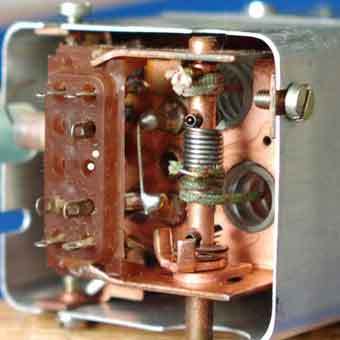
and here: 
Also when the Wheel and the shaft is not cupled,
the same result is vissible. I have make for you 3 pictures there you can see whats going on.
It is not so easy to test this, you musst open the UKW Box. Tell me please what you mean.
Best regards Hans
To thank the Author because you find the post helpful or well done.
Thank your very much for you ideas.
I checked all the things you told and everything is ok.Now i hear in all the FM scale more than one broadcast at the same time,and when I move scale the light of tube(EM 84) dosen't change.
Once more thank for our reply and the good quality photos.
Best regards
Duarte
To thank the Author because you find the post helpful or well done.
stepp 2
Hallo Mr. Duarte,
Your newest info says:
Now i hear in all the FM scale more than one broadcast at the same time,and when I move scale the light of tube(EM 84) dosen't change."
Before this:
It receives only one broadcast station in all FM scale
That's a new situation.
This phenomena is to observe, when the Cores not moved or, the local oscillator is not present. Can you give a information what FM Stations in Lisboa you receive. Most important, are frequencies with a gap of 10,7 Mcs. For example: 88,00 and 98,7 and so on.
If the local oscillator is not preset, a strong Station take over his function. We have to clear this first.
Have you realy testet the Tube ECC85 on top of the FM Box?
If I have this info, I can further thinking what is next?
Best regards Hans
To thank the Author because you find the post helpful or well done.
Lisbon FM stations
Herr Hans Knoll
Lisbon FM frequencies are the follow.
As I said before, I hear in all the FM scale two stations.
They are: TSF 89.5 and Radio Paris Lisboa 90.4.
The ECC85 was checked and also changed by a new one.
Thank You.
Best regards
José Duarte
| Frequências | Nome da Rádio |
RDS
|
|---|---|---|
| 87.6 | Rádio Seixal | SEIXALFM |
| 88.0 | Rádio Ocidente | OCIDENTE |
| 88.4 | Rádio Nato | - |
| 89.1 | Rádio Lezíria | RL-FM |
| 89.5 | TSF | TSF |
| 90.4 | Rádio Paris Lisboa | RPL 90.4 |
| 90.9 | Popular FM | POPULAR |
| 91.2 | Rádio Clube de Sintra | RCSINTRA |
| 91.4 | Rádio Iris | IRIS FM |
| 91.6 | - | - |
| 92.0 | Rádio Nova Antena | R N A |
| 92.4 | Mega FM | MEGA FM |
| 92.8 | Horizonte FM | HORIZ.FM |
| 93.2 | RFM | RFM |
| 93.7 | Rádio Mais | R. MAIS |
| 94.4 | Antena 2 | ANTENA 2 |
| 95.0 | Miramar | MIRAMAR |
| 95.3 | Tropical FM | TROPICAL |
| 95.7 | Antena 1 | ANTENA 1 |
| 96.2 | - | - |
| 96.6 | Best Rock FM | BEST FM |
| 97.1 | Rádio Viva | - |
| 97.4 | Rádio Comercial | COMRCIAL |
| 97.8 | RADAR | RADAR |
| 98.1 | Rádio Marginal | MARGINAL |
| 98.7 | Rádio Baía | RAD BAIA |
| 100.3 | Antena 3 | ANTENA 3 |
| 100.8 | Rádio Capital | CAPITAL |
| 101.1 | Romântica FM | - |
| 101.5 | RDP África | AFRICA |
| 101.9 | Estação Orbital | ORBITAL |
| 102.2 | Rádio PAL | PAL FM |
| 102.6 | Oxigénio | OXIGENIO |
| 103.0 | MIX FM | - |
| 103.4 | Rádio Renascença | RR |
| 103.9 | Sesimbra FM | SESIMBRA |
| 104.3 | Rádio Clube Português | R. CLUB. P |
| 104.8 | Rádio Eco | ECO FM |
| 105.4 | CSB Rádio | CSB |
| 106.2 | - | - |
| 107.2 | Rádio Cidade | CIDADE |
| 107.7 | Rádio Nossa | - |
To thank the Author because you find the post helpful or well done.
FM Box measurments
Hallo Mr. Duarte,
attached you find a diagramm, i think is the same as in your set.
Please see two Resitors outside of the BOX in this case 8,2 and 33 kohms.
These values depends from the Supply Voltage off each set.
Please oberve and meassurments the Voltage befor and behind off each Resistor.
The current you can see shut be aprox. 12 and 3,75 mAmps.

NEW:
meanwhile send our Member Mr. Eckhard Kull the orig. Telefunken UKW Box of OPUS 2004
The quality is not so good ( its a long journey to me) its only for refence. 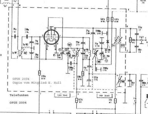
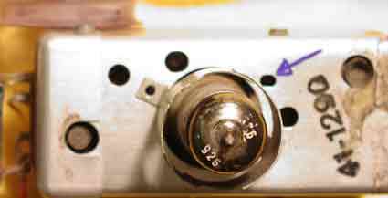
Blue arrow= testpoint -Uosc. FM local oscillator
New at 1.02.05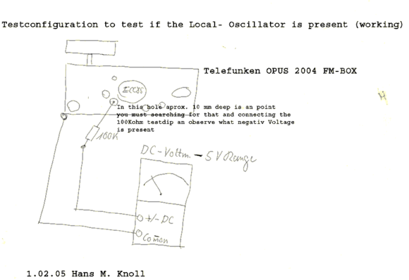
I think your 4,5 are to high. Maybe the oscillator do not work.
Use this test to measure the negativ voltage on G1 ECC85 II .
If all O.K. the negativ voltage shut be -2 to -3 volts.
Further you have not answer to Post 5 (moving the cores)
Additional dit you hear the two FM Stations over the whole scale left to right .
How loud is the noise on FM Range much more then on MW?
Its hard job to find whats wronge!
Hans M. Knoll
To thank the Author because you find the post helpful or well done.
I measured and the values are 9mAmps and 4,5mAmps
THank you once more
Best regards
Duarte
To thank the Author because you find the post helpful or well done.
FM BOX ?
i think this 4,5 mA are to high. See my alternations on post 8.
Knoll
To thank the Author because you find the post helpful or well done.
Hallo Herr Hans Knoll
-The core's cord is OK it works fine.
- The tensions in 33kOhm resistor are 235V and 84V. So (235-84)/33000= 4,5 mAmp
- The two stations are listened in all scale, mixed and not very clear,. MW is heard much louder than FM.
Now the negative voltage on G1 ECC85 II:
It was measured 0,00V but..
When I put the lead terminal inside the hole of the test point, I can hear one station very loud and clear. If I take it off from the hole the tune stands still.
If I turn the tune knob searching another station along the scale, the tune is lost.
But if I put the lead terminal again, with some luck I can hear another station. Also this new station is heard loud and clear and stands still even after I take off the terminal.
To thank the Author because you find the post helpful or well done.
Local Oscillator not works.
Hello Mr. Duarte
Its fine you make a good job Result is, local Oscillator dues not working.
Next and I think last, you have to test, is a connection between pin 7 ECC85 and ground. Remove the Tube and measure the resistance from pin 7to ground. The value must aprox- 330Kohm. If not, the red marked coil is disconnected . 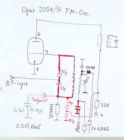
In my sample, all red marked condensers are high quality ceramics.
I have no idea why one of these in your set, its maybe wrong.
Fist the 11 pf and 125 pf are important.
You can try to put an 10 to 15 pf (green marked) from test point to Case You remember, the Test dip makes an action.
Next important is the 2200pf. ( red ). It is your decision , how to shunt a 2200 pf for the moment, to this .( its all in Box) !
If all this without responding, I have not any idea in the moment. I am sorry
Best regards, Hans M. Knoll
To thank the Author because you find the post helpful or well done.
Hello Herr Hans Knoll
Sorry for this so late reply. You can understand. I needed a lot of nerve to unwire and open FM case again.
I thank you again for your patience.
I still wonder why it works so good when I touch the test point and it stands working after I take the pointer out. What is the phenomenon?
The measurers you ask me to do are:
Between pin seven and test point ----------- 330 kOhms
Condensers:
11pF ------------ 16pF measured
125pF-------------126pF measured
The test with 10 pF between test point and earth didn't produce any effect.
The two 7,5 pF presents 8,2 pF measured
I also had made some more checks:
Diode is OK
In pin 2 : 330pF ---- 382pF measured
11pF ---- 6,3pF measured
Resistor 220kOms---237kOms measured
That's all
It's being hard so I must thank you again for your comittement.
Best regards
Duarte
To thank the Author because you find the post helpful or well done.
Osc Test without results.
It's being hard so I must thank you again for your comittement
Mr Duarte,
this results < 330 Kohm> are imposibile.
you:
Between pin seven and test point ----------- 330 kOhms
mee: Only if Coil is interruptet,, and Pin 7 is groundet,, or ECC85 is heated.
Pin 7 and Testpoint is conected only thru the red marked Coil.
Lower then one Ohm must be measured.
And what is with this Condenser? Next important is the 2200pf. ( red ). It is your decision , how to shunt a 2200 pf
I am sorry, you must or not?
Hans M. Knoll
To thank the Author because you find the post helpful or well done.
Herr Hans Knoll
Of course it was a mistake. I'm deeply sorry.
330kOhms was measured between pin 7 and earth.
About shunting the 22000pF condenser:
At time I did not understand that it was important do it before a further measuring inside the box.
Of course I'll do it next.
Next step: I will shunt the condenser; I'll close the box and I'll make provisory link wires to check it before definitive assembling.
I'll tell you the results in next article.
Best Regards
José Duarte
To thank the Author because you find the post helpful or well done.
What is to do next?
I think, you can test the FM Box outsite of the Set.
Is only necessary : DC 220 Volts , AC 6,3 Volt and Earth.
Also without the Case.
The only failure is at moment, the Local Osc. to not works. To test, 2 to 3 Volt negativ an Testpoint is necessary!
The 2200 pf is inline with the Osc- Coil and one Part of the Circuit. If these is bad, no oscillation is possible. I now, it is a hard job. Fact is, no Oscillation, no reception.
All other Phenomenas , i dont now what is audible. Can you tune different Stations in this case?
The Testpoint is the one and only sesitivest Point in the whole set.
All frequencies find an Input there.
Regards Hans M. Knoll
To thank the Author because you find the post helpful or well done.
Hello Mr. Hans Knoll
I already made a shunt between 2200pF and earth -- nothing happened differently.
I disconnected it and the situation is the same as I told you before:
No tune in, except when I touch the test point.
Such as:
If the variometer is in its right place (near of a station), I touch the test point and that station immediately can be received.
It is going on working in excellent tune even after I take off the touch. It stands well. Radio set seems to be in perfect conditions, until...
Afterwards I displace the position of variometer. The tune in of this station disappears. It is normal. But..
Afterwards I displace the variometer to another tuning point (another station). Nothing happens... until I touch again the test point. When I do it, that new station can be received loud and clear.
And so on.
Thank you for your patience
Best regards
José Duarte
To thank the Author because you find the post helpful or well done.
Before I write an actual report, please make this additional Test
remove ( resolder ) the two wires from FM Box to the Chassis in this small drawing market
< X> and <X> this is the AFC Controll.

I think at moment the failure is outsite off the BOX.
New at 16.02. 17:00


This is the AFC Circuit. Please check the red market Resistors partikular the 1Meg Ohm
Your newest Test give me this idea.
More infos after you have testet.
Regards Hans
To thank the Author because you find the post helpful or well done.
hans
To thank the Author because you find the post helpful or well done.
Hallo Mr. Hans Knoll
At last the guilty one was discovered. One 3Mohms resistor is opened.
I followed your advices and I tested the resistors near EABC80. Here it is one 3Mohms not a 1Mohms linked to 210V. I changed it and now all is OK.
Congratulations .Set is now working . Thank You very much.

Best Regards
José Duarte
To thank the Author because you find the post helpful or well done.
Final.
20 Posting for one Resistor! Mr. Knoll you get old!
Mfg Knoll
To thank the Author because you find the post helpful or well done.
Hallo Mr.Hans Knoll
In my opinion 20 posting were not because Mr. Knoll is getting old.
It were because his interlocutor is "too young" in this matters.
Some clues sent, were not enough clear to one reach to a quick diagnosis.
Best regards
Jose Duarte
To thank the Author because you find the post helpful or well done.
Compliments to both Gentlemen

I am sure that Herr Knoll knows of the "blind squirrel" cases - when he must dig many times to find the acorn. But, he does not quit, because he knows it is somwhere close.
After many days, I found marginal solder connection within FM pre-amp cage which was sensitive "thermal increase" and then FM stereo went off. Also happened on several other Sansui 1000A receivers built within short time period.
Senor Jose Costa, you are to be commended for displaying persistence with patience.
I am absolutely amazed at the wonderful use of text and the hand-drawn graphics blended together by Herr Knoll. We are indeed honored to follow your performances. The master of a slide rule has mastered the "cyber" rules!!
Un ablazo para Jose,
und mit Viele Grusse to Herr Knoll,
Respectamente,
Robert Sarbell
To thank the Author because you find the post helpful or well done.
at last.
Hello Robert,
i thank you for your friendly comment. I think, you can realize , how many thought are necessarry to bring it forward.
For your Eyes, you remember? Here 66 2/3 % "oldgemany" and 33 1/3 % "USA" .This are my tools, to search resistors. ;-)

Best regards , Hans
appendix:
oh, Robert i see!
you mean this one: 
yes, this here was my first "TEXAS" for 298,00 DM!
Hans
To thank the Author because you find the post helpful or well done.
Vintage Calculators for Vintage Calculaters
Yes, many years ago they get much use. But your Texas Instruments is LCD screen. . . .surely your first hand held calculators is using only small LEDS. . . .and not so many trigonometric functions - many tables for that. Even my teacher Herr Kirst did not have hand-held electronics in 1959.
Respectfully,
Robert Attachments:
- Vintage Calculators (43 KB)
To thank the Author because you find the post helpful or well done.