100% Digital Phase Shift Oscillator...
100% Digital Phase Shift Oscillator...
Fellow Radiophiles:
My good friend Jack Memishan, who is a leading analog engineer, gave me the wonderful Ice-clock kit using the very nice IV-18 Russian Vacuum Fluorescent Display (VFD). This 8 digit display tube is obsolete, but new-old-stock samples can still be found for sale.
Jack's thoughtful gift inspired me to build for him something 100% digital with the IV18 display tube. This gadget should show off the pretty glow of this display tube and also be fun to watch; well, fun for someone with a technical sensibility. I decided to implement the digital aspect of this gadget by using only digits as active elements instead of using logic gates, which is the conventional digital approach.
VFD displays that are designed to be driven in multiplexed arrangements employ a selection grid between the filamentary cathode and the glowing anode segments. The electrical transfer function of VFD displays with a selection grid is the same as a triode with filamentary cathode.
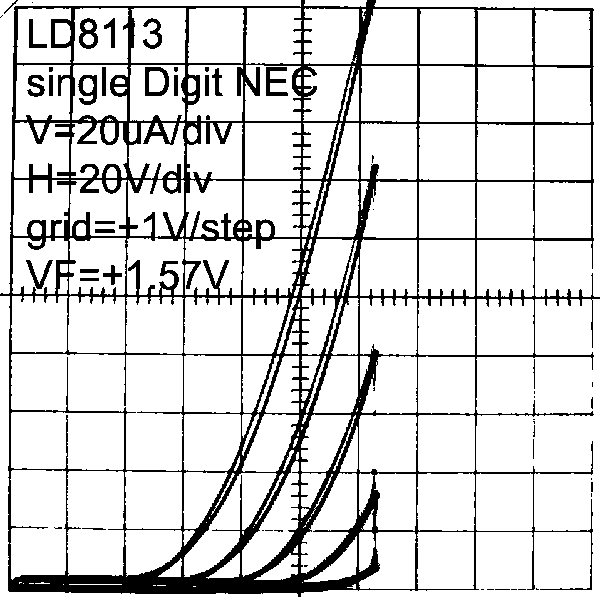
One example of a single VFD digit with grid control is the LD8113 made by NEC.
The following two curve trace plots show the triode operation of the LD8113 with the grid in reverse bias steps and in forward bias steps:
Individual digits in the internally multiplexed multi-digit IV-18 have a similar characteristic. In the case of the IV18, each control grid controls a single digit. The seven segments that make up each digit are wired in a parallel bus. This way, any combination of segments (anodes) can be lit up for a single digit when that digit's control grid is enabled high.
The intended operating range for most VFD displays is with a low Anode (glowing segment) voltage and a positive control grid voltage, as shown on the right plot above. This mode of operation uses lower anode voltages to obtain normal phosphor glow at the expense of relatively high driving power into the positively driven digit control grids. When the control grid is forward biased like this, it operates like a space charge grid that accelerates the cathodic space charge to the low voltage anode.
The more conventional triode curve sweep on the left with negative control grid steps shows the region of operation that is used for most triode based amplifiers and oscillators. However, much higher anode (glowing segment) voltages are required for current flow as can be seen that no current flows below 120V at the anode on the left plot.
VFD displays can be used as triodes in conventional amplifier and oscillator circuits. TRF radios from the 1920's are possible candidates for experimentation with these VFD tubes as triodes, but keep in mind that the transconductance of the VFD tubes can be quite low. The LD8113 only has 70uS, while a 1920's triode had something like 500uS. In addition to the amplification and oscillation, you can also observe the effect of these signals on the glowing segments of the anode, if the signals are not too fast for the eye to follow.
The 100% Digital Phase Shift Oscillator
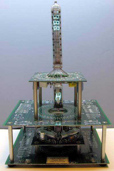
 I wired the LD8113 VFD as a triode in a classic phase shift oscillator operating with a period of a few seconds, so the cyclical variation of current in the Anode segments can be observed directly. The LD8113 is shown as the single digit below the IV18 8 digit display.
The classic phase shift oscillator consists of an inverting amplifier with enough gain to overcome the losses of the multi-stage phase shift network that achieves 180° of phase shift in it's feedback path.
In this particular implementation, the phase shift network consists of 6 stages that contribute about 30° of lead phase shift individually, for a total phase shift of -180°. The attenuation at the frequency that produces this phase shift is about 1/6. The triode is thus biased for a gain of approximately 6 to maintain oscillations around the feedback loop.
The function of the 8-digit IV18 display is to display the oscillation at each stage of the 6-stage phase shift network. While the single digit LD8113 serves as oscillator and displays it's own oscillation, the 8-digit IV18 operates strictly as a display device.
During operation, the LD8113 will light up and extinguish it's glow with it's own oscillation over a period of about 10 seconds. The monitoring IV18 displays the progress of the phase shift network as a smooth vertical glow motion from the bottom of it's 8 digits towards the sign position at the top.
The IV18 has altogether 9 positions with 8 digits plus sign, but there are only six stages to monitor. What to do with the remaining 2 digits plus sign? I added three stages of 30° phase lag to simulate the wave motion before the start of 6-stage phase lead feedback network. (Click schematic to enlarge)
The top row of Triodes in the schematic represent the 8 digits plus sign of the IV18. Note how their grids are all connected to taps in the 6 stages of the lead feedback network and 3 additional lag stages. The net phase shift covered by these 9 stages is on the order of 270°-300°. The grids of the IV18 are connected to taps in the lead network to attenuate the full swing of the particular stage to suit the 30Vp-p swing that drives the negatively biased IV18 grids. The p-p swing at the anode of the LD8113 is 170Vp-p and it decays to 30Vp-p with 180° phase shift by the time it reaches the grid of the LD8113.
The amplitude regulation of the LD8113 oscillator circuit is done with soft limiting by the LD8113 square law content of it's voltage transfer function.
Both VFD tubes are operated with negative grid bias. This explains the relatively high Anode supply voltages of 500V for the LD8113 and 285V for the IV18. The operation of these tubes at high voltage and low current helps extend the life of the segment glow. See this post on how to light up dark eye tubes for the effect of current and voltage on the life of tubes with fluorescent anodes. (Click thumbnails to enlarge)
You can view the 100% Digital Phase Shift Oscillator in operation on Youtube.
You may also enjoy taking a look at an earlier Phase Shift oscillator that I built with the DM160 VFD triode a few years ago, see www philbrickarchive.
Best Regards,
-Joe
Attachments:To thank the Author because you find the post helpful or well done.


