A Simple Battery Shortwave Superheterodyne Receiver
A Simple Battery Shortwave Superheterodyne Receiver

The receiver presented here is the outcome of several months of "homebrewing" development and
testing. It is presented in great detail in the hope that this might be interesting and useful for other vintage radio homebrewing enthusiasts.
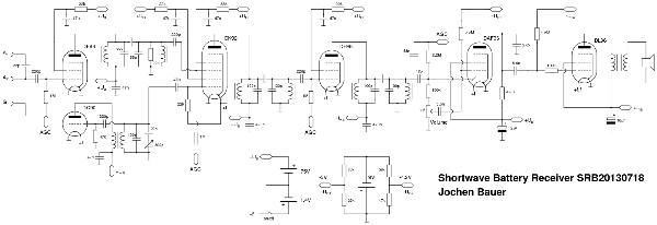
Below is a small size version of the circuit diagram. The full size version is attached to this article as a PDF.
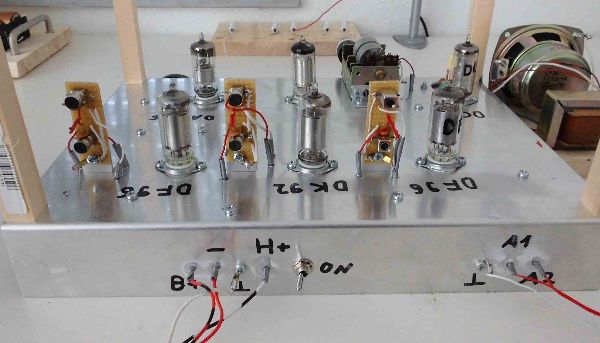
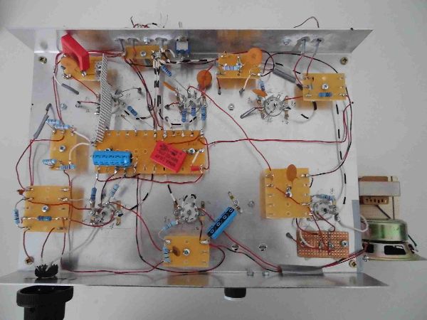
Let me show two pictures of the receiver. Note that the posts on each corner are used for turning the chassis upside down without the need for a cradle.
This is the top view:
And here is the bottom view:
I would now like to give a detailed description of the design and the thoughts and ideas behind it.
There's a myriad of receivers of all types that can be build in a homebrewing project. To get started, we need to make some decisions on what to build and how to build it.
First of all, we need to pick a frequency range for our receiver. A great number of homebrewing projects (in particular for beginners) focus on the medium wave range, also known as the AM broadcast band. However, with fewer and fewer medium wave broadcast stations remaining in Europe, focusing on the worldwide shortwave broadcast bands seems to be a worthwhile alternative.
Also, we need to decide whether we want to build a simple Tuned Radio Frequency (TRF), possibly
with regeneration or a Superheterodyne receiver. Both technologies have their merits. In particular the regenerative TRF receiver can deliver an amazing performance at shortwave frequencies. However, the decision here will be to build a single intermediate frequency superheterodyne receiver. This an "in the middle" approach between a simple TRF receiver and a double superheterodyne receiver using two intermediate frequencies (IF), one high IF for image frequency rejection and one low IF for good selectivity.
Now we can come to the considerations on what tube types to to use. This, again, is entirely a matter of taste. The decision here is to use D-series battery tubes, in particular the DF96, DC90, DK92, DAF96 and DL96. The DK92 is preferred over the DK96 because it is available at a much cheaper price. The filament voltage of these tubes is 1.4V, suitable for batteries with a nominal output voltage of 1.5V (A-battery). The positive supply rail voltage for these tubes (B-battery) is typically 60V to 90V. This choice provides us with the following advantages:
- Simple design, no power supply unit (transformer, rectifier tube, filter choke and capacitor)
is needed.
- Can be used outdoors, away from sources of electromagnetic noise (switched mode supply
units, powerline ethernet, etc...)
- The positive supply rail voltage falls well within the Extra-Low Voltage (ELV) range of less
than 120V DC making dangerous electric shocks unlikely
Commercially available battery tube receivers in general avoided the use of a C-battery providing a negative voltage for grid biasing. Instead grid leak biasing for the DAF96 and common cathode
resistor biasing for the DL96 were commonly used. This is due to the fact that the need for a third battery would have been a marketing disadvantage. Since such constraints do not apply to
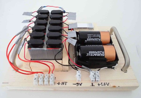
homebrewing, a 9V C-battery is used. The B-battery is made of 12x9V batteries in series, with taps at battery #9,#10 and #11, allowing to maintain an output voltage of between 70V and 80V as the batteries deteriorate. The nominal positive supply rail voltage is arbitrarily set to 75V. The batteries are shown in the picture below.
As far as the mechanical setup goes, there seems to be a choice between a breadboard setup with
the tube sockets along with the other components mounted on top of a wooden board and a metal
chassis setup. In the course of developing this receiver it turned out that adequate shielding to avoid undesired oscillations in the IF amplifier is only possible with a metal chassis setup. More on this can be found in the section on the IF amplifier.
When acquiring parts for vintage radio homebrewing it quickly turns out that suitable RF coils and IF bandpass filters for tube radios are quite difficult to obtain. This can be attributed to the fact that, unlike tubes, coils and IF filters are not expendable parts and therefore there has been no huge stock for replacement purposes in the past. At this point it needs to be pointed out that readily available IF filters for (bipolar) transistor radios from the 60s and 70s are not suitable for our purposes. The reason is that with tube amplification stages it's (almost) all about voltage gain. To achieve a high voltage gain the tuned circuits used as plate loads must have a high L/C ratio. Transistor radio 455kHz IF filters composed of two coupled tuned circuits sometimes use capacitors as large as 2000pF, making the L/C ratio very unfavorable for tube based amplification stages. A typical filter for an IF in the 450kHz range employed in tube radios uses capacitors of around 100pF, requiring a coil inductance in the 1200uH-1300uH range.
The first option here is winding the needed coils yourself. However, coils with an inductance over 1000uH and a Q-factor of roughly 100 that still have dimensions making them suitable for use in IF filters require the use of mechanical winding machines possibly not available to the hobbyist.
Another option is to use readily available "mini-coils" originally intended for printed circuit boards. These coils are wound around a ferrite core inside a ferrite pot making them magnetically shielded from the environment. The inductance of these coils can be adjusted within certain limits by moving the pot closer to or away from the core. These mini-coils come with inductances from 100uH to 2000uH and with Q-factors ranging from 50 to 100. While the two tuned circuits in vintage IF filters are usually coupled inductively (hence the name "IF-transformer"), this is not possible with tuned circuits employing magnetically shielded coils. Therefore, one has to revert to capacitive coupling as shown below. IF and RF bandpass filters build with such mini-coils can be seen on the above top view picture of the receiver.
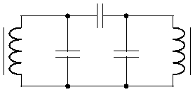
The coupling capacitor needs to be quite small for critical or slightly overcritical coupling and hence it is common in homebrewing to build such a capacitor using a pair of twisted wires. By twisting/untwisting the wires the capacitance even becomes adjustable. This simple capacitor is often called a "twist-o-tweak" (thanks to Joe Sousa for pointing this out to me). Integration of such an inductively coupled bandpass filter into a tube amplification stage is quite simple as can be seen from the circuit diagram of the receiver. Bear in mind that the positive supply rail voltage is AC-grounded.
At this point, we need to make some considerations on the maximum L/C ratio, respectively on the
minimum capacitances we can use in the tuned circuits (bandpass filters and oscillator circuit). As far as voltage amplification goes, the smaller the capacitance and the bigger the inductance, the better. There are, however, two limiting factors: First, with the capacitors getting smaller, the stray capacitances in the mechanical setup become more and more important. This makes controlling the circuit's parameters more and more difficult. For example, moving a wire a little closer to the chassis might result in a considerable resonant frequency shift of a tuned circuit. Second, performing measurements on the tuned circuits without overly altering the resonant frequency becomes a problem since even a loosely coupled probe will significantly alter the capacitance of the tuned circuit. Hence, we shall make the decision to not use capacitors smaller than 50pF in tuned circuits as can be seen from the circuit diagram of the receiver.
With the idea of what coils to use and how to build bandpass filters settled we can now move on to designing the RF input stage of the receiver. In the medium wave range the input tuned circuit needs to cover a wide (relative) frequency range. It roughly needs to go from 500kHz to 1700kHz, that is a bandwidth of 1200kHz around a center frequency of 1100kHz. This requires the input tuned circuit to be ganged to the oscillator tuned circuit, typically using a gang capacitor. In the shortwave range, however, the relative bandwidth of the broadcast bands is much smaller. For example, the 49m broadcast band ranges from 5950kHz to 6200kHz, that is a bandwidth of 250kHz around a center frequency of 6075kHz. These relatively small bandwidths make it possible to waive a ganged variable frequency tuned circuit and instead use a fixed frequency input bandpass filter for a given shortwave band. This leaves us with the oscillator tuned circuit as the only variable frequency tuned circuit, greatly simplifying our design. At present, changing the RF input filter and the oscillator tuned circuit in order to listen to a different shortwave band requires some soldering. A goal for an improved design would be to make those two "modules" simply pluggable.
Typically in combined long- medium- and shortwave receivers the antenna is coupled inductively or capacitively to the first tuned circuit that is also the input tuned circuit of the mixing (frequency conversion) stage. To limit damping and detuning of the tuned circuit caused by the antenna, the coupling has to be loose. The idea here, however, is to use an RF amplification stage before the mixing stage. That is, the antenna signal is fed into the input of the RF stage and at it's output is the tuned circuit that is the input of the mixing stage. It should be noted that since this setup requires one more (expensive) tube it is rarely found in vintage consumer-grade receivers. In our case, the tuned circuit is one of the two capacitively coupled tuned circuits forming the RF bandpass filter for the respective shortwave band we want to listen to.
This receiver is intended to support two different antenna types, the electrically short (shorter than a quarter wavelength) random wire antenna on jack A1 with real or counterpoise ground connected to G and the tuned magnetic loop antenna connected across jacks A2 and G.
Let's start with the electrically short random wire antenna:
To get the most voltage at the endpoint of a short random wire antenna, the input impedance of the
RF stage needs to be as high as possible. Therefore, the antenna is connected to the grid of the RF
stage tube. (Note that here we are interested in voltage transfer and not power transfer which would require impedance matching.) For improved performance, the chassis (jack G) should be connected
to real ground (earthing) or a counterpoise ground.
There is one disadvantage of this setup: Any random wire antenna connected to a high impedance input with ground provided to the receiver either by real ground (earthing) or a counterpoise ground is prone to picking up 50/60Hz mains hum from the environment. Although these low frequencies are almost completely rejected by the bandpass RF filter in the plate circuit, they would still interfere with the input signal since the DF96 is a variable transconductance pentode designed for gain control by the grid bias voltage. Hence, a mains frequency grid voltage change would result in the output signal of the RF stage being amplitude modulated (through the gain control feature of the tube) with the mains frequency, resulting in audible hum after detection.
Therefore, to be able to use the receiver with a random wire antenna any mains hum picked up needs to be attenuated to a reasonable level at the grid. This is accomplished by connecting small capacitors between the antenna and the grid. Antenna jack A1 has an additional 22pF capacitor in it's path resulting in a jack to grid capacitance of approximately 20pF. This capacitance forms a low-pass filter with the 1MOhm grid bias resistor rejecting mains hum frequencies. For example, at 50Hz the 20pF jack to grid capacitance has a reactance of 160MOhms, thus attenuating hum by a factor of almost 1/160. Note that the 3.3pF grid capacitance of the DF96 results in a reactance of almost 1000 MOhm at 50Hz and can therefore be neglected. At shortwave frequencies, the reactance of those capacitors is considerably smaller. The 3.3pF grid capacitance gives rise to a reactance of 8kOhms at 6000kHz (49m band) and therefore the 1MOhm grid bias resistance is now neglectable, leaving us with a capacitive voltage divider made of 20pF jack to grid capacitance and 3.3pF internal grid capacitance. Hence, if A1 is used, shortwave frequencies will only be attenuated by a factor of approximately 0.86.
While the electrically short random wire antenna is simple to set up and provides a relatively
high input RF voltage, it is prone to picking up electric near-field noise from various sources
being present in a typical household. The tuned magnetic loop on the other hand is less prone to
local electric interference (including mains hum) and often has a better signal to noise ratio
(SNR). We'll get the best performance from a tuned magnetic loop if the input impedance
of the RF stage is as high as possible (bear in mind that the input impedance is a parallel loss
resistor to the tuned loop). Therefore, the tuned magnetic loop is also connected to the grid
of the RF stage tube. Here, however, we do not need any additional capacitors for hum rejection.
Furthermore, the chassis can be left "floating" i.e. it does not need a ground connection.
Designing the rest of the RF input stage is fairly simple:
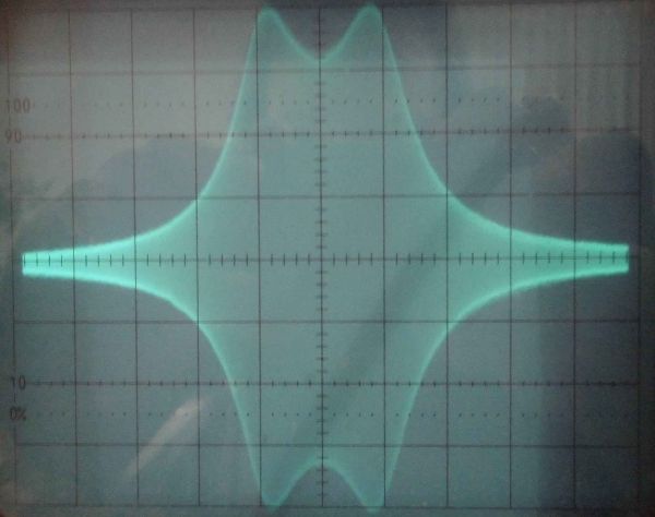
The recommendations in the datasheet of the DF96 for the screen (grid #2) resistor are 39kOhms for a positive supply voltage of 85V and zero for a positive supply voltage of 64V. Since our circuit is designed for 75V, we'll use 22kOhms. Furthermore, the screen and positive supply rail are AC grounded by a 47nF capacitor located close to the tube. The pass-curve of an RF input filter for the 49m shortwave band is shown below. The -3dB bandwidth is approximately 250kHz around a center frequency of 6075kHz, nicely covering the 49m broadcast band. The 22kOhms damping resistor across the secondary tuned circuit turned out to be necessary in order to prevent the center dip from being below the -3dB limit.
At this point it seems appropriate to make some remarks on measuring pass-curves for RF and IF
bandpass filters by doing an input frequency sweep: The main problem here is the speed at which the frequency sweep is done. A driven tuned circuit needs some time to settle if the frequency or the amplitude of the driving voltage is changed. This time span depends on the resonant frequency and the Q-factor of the tuned circuit. The lower the resonant frequency and the higher the Q-factor, the longer it takes for the tuned circuit to settle. If the frequency sweep is done too quickly, it will yield a deformed pass-curve. While the maximum sweep rate can be calculated from the properties of the tuned circuit, there's also the following experimental approach: Here, the pass-curve is displayed on an analog oscilloscope with a traditional luminescent screen. The sweep control curve is set to triangular, so that the up-sweep time is as long a the down-sweep time. In this setup, a too short sweep time will result in "ghost images" on the luminescent screen stemming from the fact that the up-sweep pass-curve is different from the down-sweep pass-curve. The sweep time is then gradually increased until the up-sweep and down-sweep pass-curve shapes converge and the ghost images vanish. There is one more problem: At very long sweep times (low sweep frequency) the AGC (Automatic Gain Control) feature of the receiver will interfere and the pass-curves will get deformed again. This can be avoided by grounding the AGC output after the 2.2MOhms resistor, therefore setting all grid bias voltages to zero which is permissible according to the datasheets of the DF96 and DK92. The input voltage now, however, needs to be as small as possible.
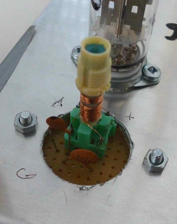
The oscillator uses a DC90 VHF triode originally developed for self-oscillating mixing stages in FM receivers. It'll do nicely for the standard Armstrong/Meissner oscillator circuit that has been employed here. The 47kOhms grid resistor is chosen so that the amplitude of the oscillations are approximately 4V RMS (11.3Vpp) as recommended in the datasheet of the DK92 frequency mixing octode. The inductance, parallel and series capacitor of the tuned grid circuit need to be chosen according to the shortwave band we want to listen to. The variable capacitor is a standard 300pF gang capacitor with only one section used. The inductor along with the feedback coil (tickler) is wound on a ferrite core former that has originally been a 10.7MHz FM-IF filter for transistor radios. Like the mini-coils, these coils are also readily available. The coil along with parallel and series capacitor is shown in the picture below. Again, changing the tuned grid circuit for listening to a different shortwave band requires some
soldering. A future improvement might be a fully pluggable tuned grid module.
The mixing stage uses the DK92 octode in a circuit that is presented in the Philips datasheet for this tube with the oscillator connected to grid #1 and the RF input at grid #3. Grid #2 and grid #4 resistors have again been adapted to a positive supply rail voltage of 75V. The plate load of the DK96 is one of the two capacitively coupled tuned circuits forming the first IF bandpass filter. The IF frequency has been arbitrarily set to 470kHz.
Following the mixing stage is the IF amplifier stage making again use of the DF96 pentode in a setup similar to the first RF stage. The plate load of the DF96 is one of the two capacitively coupled tuned circuits forming the second IF bandpass filter. Since at the input and output of this stage there are tuned circuits of the same resonant frequency, this stage requires proper input to output shielding to avoid undesired oscillations. While experimenting with this IF amplifier stage it turned out that the main problem is the external Miller capacitance between the grid and plate pins of the tube socket respectively the leads of the components connected to those pins. Proper de-coupling of the input and output side of the DF96 was achieved by mounting a metal shield (approx. 3cm high and 8cm long) across the socket, separating the grid circuit from the plate circuit. The DF96 has two negative filament pins that form a straight line with the center post of the tube socket. This line separates the grid pin from the screen and plate pins and the shield can be mounted along this line.
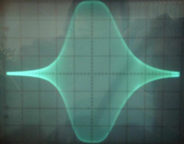
The overall IF bandpass curve of the IF amplifier is shown in the following picture. The -3dB bandwidth is 7.7kHz, resulting in an audio frequency (AF) bandwidth of 3.35 kHz which is certainly ok for our purposes here. Bear in mind that shortwave programming is mostly talk, information and news with only little music. The IF bandpass curve is still a little asymmetric, indicating that some more fine tuning of the IF part might be necessary.
This is a good point to present some general considerations on performing measurements in the RF
and IF part, in particular probe coupling and undesired detuning of tuned circuits. Since even a 1:10 voltage divider oscilloscope probe has a typical input capacitance of 16pF, connecting a probe directly to a tuned RF or IF circuit will severely lower it's resonant frequency. Calculating the impact of the probe's capacitance on a tuned circuit is fairly easy. Since the resonant frequency is f=(1/2pi)*sqrt(1/LC) an additional capacitance Ca, increasing C to C'=(1+Ca/C)*C will change the resonant frequency to f*sqrt(1/(1+Ca/C)). For example, if C=100pF and Ca=16pF the new resonant frequency is f*0.93. For an IF tuned circuit with f=470kHz, the new resonant frequency would be 437kHz, that is a severe detuning. From this it becomes clear that there a basically two options. First, the probe is considered to be a part of the tuned circuit and (making use of the adjustable coils) the tuned circuit is re-aligned with the probe present. Second, the probe is coupled very loosely to the tuned circuit. "Very loosely" in this case can mean anything from barely touching the insulation of a wire to merely being in the vicinity of that wire. Again, there is a simple experimental method to determine the point where the coupling is sufficiently loose: The pass-curve of the tuned circuit is displayed on an oscilloscope while the distance of the probe from the wire is increased. The point from where on a further increase in distance does no longer alter the resonant frequency (respectively the shape of the pass-curve) but only affects the amplitude of the pass-curve is the point of sufficiently loose probe to circuit coupling.
Using the first coupling method described above (re-alignment with the probe connected) we are able to determine the maximum (AGC disabled) overall voltage amplification factor of the RF/IF part to be around 11000. Bear in mind that the RF stage contributes very little to the overall amplification factor since at 6MHz it has a very unfavorable L/C ratio. It's main purpose is indeed image frequency rejection and decoupling the antenna from the input bandpass filter. As it turns out, even when using the tuned loop antenna, the acoustic noise coming from the speaker with the receiver tuned between radio stations has approximately the same volume as the audio signal coming from radio stations. This is a clear indication that there is sufficient maximum amplification and the actual amplification factor is controlled by the AGC. From this point on, any improvements need to focus on the signal to noise ratio of the antenna and the receiver.
Let us now return to the circuit description: Detection is performed by the diode section of the DAF96 that is connected to the secondary tuned circuit of the second IF bandpass filter via a 47pF capacitor. The discharge path of this capacitor is through a 100kOhms resistor in series with a 1MOhms potentiometer that serves as the volume control. The time constant of this RC combination is t=R*C=52us resulting in a corner frequency of f=1/(2*pi*t)=3.1kHz that goes very nicely with our goal to limit the audio bandwidth to about 3kHz for the sake of better selectivity. The AF signal is taken from the volume control tap of the 1MOhms poti and sent to the grid of the pentode section of the DAF96 via a 5.6nF coupling capacitor. The 100kOhms resistor prevents the grid of the pentode section from becoming a part of the detection circuit, altering it's parameters, if the volume knob is turned to maximum. To obtain the automatic gain control (AGC) voltage, the full voltage at the DAF96's detection diode is sent over a lowpass filter made of a 2.2MOhms resistor and a 68nF capacitor. This lowpass filter has a corner frequency of approximately 1Hz making it impervious to audio frequency signals but still enabling it to react to fading and other changes in the input RF signal.
Biasing of the DAF96's pentode section that acts as the AF pre-amplifier is done by a fixed bias
voltage of -3V created by a voltage divider from the 9V C-battery and supplied to the grid through a 2.2MOhms resistor. The screen grid of the pentode is connected directly to the positive supply rail voltage that is AC grounded by a 10uF capacitor located near the tube. The plate load is a 470kOhms resistor while the 27pF capacitor connecting the plate to ground suppresses remaining IF frequencies. The grid bias voltage is chosen so that a voltage drop of approximately 30V occurs across the 470kOhms plate resistor, setting the plate quiescent to 45V with a plate current of 60uA which is a typical quiescent plate current for this tube according to the datasheet.
The output of the AF pre-amplifier is fed to the grid of the DL96, serving as the AF power amplifier, via a 5.6nF coupling capacitor in series with a 100kOhms resistor. This resistor forms a low-pass filter with the grid capacitance of the DL96 and is a general precaution (frequently used in electric guitar amplifiers) against high frequency oscillations of the AF stage. The DL96's grid is biased with negative voltage created by a voltage divider from the 9V C-battery and supplied to the grid through a 1.8 MOhms resistor. The DL96's datasheet suggests a grid bias of -3.3V for a positive supply rail voltage of 64V and a grid bias of -5.2V for a positive supply rail voltage of 85V. Since our (nominal) positive supply rail voltage is 75V, we'll use a grid bias of -4.2V. The AC plate load of the DL96 used in a class-A power amplifier circuit needs to be between 13kOhms and 15kOhms depending on the positive supply rail voltage (refer to the datasheet). The nominal impedance of the speaker and the output transformer's primary to secondary ratio needs to be chosen accordingly. The screen (grid #2) of the DL96 is connected directly to the positive supply rail voltage that, again, is AC grounded by a 10uF capacitor located near the tube.
Attachments:
- Circuit Diagram (14 KB)
To thank the Author because you find the post helpful or well done.
A Horizontal Magnetic Loop Antenna

As mentioned in the previous post, the magnetic loop antenna usually has a much better signal to
noise ratio (SNR) than the electrically short random wire antenna. This is due to the fact that, as a magnetic antenna, it is mostly impervious to electric near-field noise. One should, however, be aware that the near-field of an interference source is anything significantly closer than a quarter wavelength. Of course, in the 49m shortwave band, a quarter wavelength is roughly 12 meters. After the near field comes the so called transition zone and finally at distances of greater than approximately five times lambda (roughly 250m for the 49m band) we are in the far-field where noise emanating from a specific source is arriving as electromagnetic waves. Here at first, magnetic antennas will pick up as much of the noise as electric antennas.
However, there's a property of magnetic loop antennas that can be used for far-field noise suppression. A magnetic loop has an easy to change orientation in space and therefore can be used as an electromagnetic wave polarization filter. The voltage picked up from the magnetic field of an incoming electromagnetic wave is at it's maximum if the magnetic field vector is perpendicular to the loop's plane. Since in plane electromagnetic waves the electric field vector (which defines the polarization) is perpendicular to the magnetic field vector, the voltage pickup will peak when the electric field vector is parallel to the loop's plane.
As it turns out experimentally, a vertical magnetic loop is picking up much more noise than a horizontal magnetic loop (at least at my place...). The conclusion here is that electromagnetic noise in the lower shortwave bands seems to have a predominantly vertical polarization. An explanation could be that in build-up areas man-made noise is the predominant type of noise in the lower shortwave bands. Most man-made noise is coming from sources like switched mode power supply units, plasma TVs, powerline ethernet, etc.. These sources all produce high-frequency voltages that have a ground (earth) reference. Therefore, seen from a distance, the noise source produces an oscillating electric field roughly perpendicular to the earth's surface along with a small alternating current in this direction giving rise to vertically polarized electromagnetic ground-waves. A large number of such noise sources would then create a predominantly vertically polarized electromagnetic noise floor.
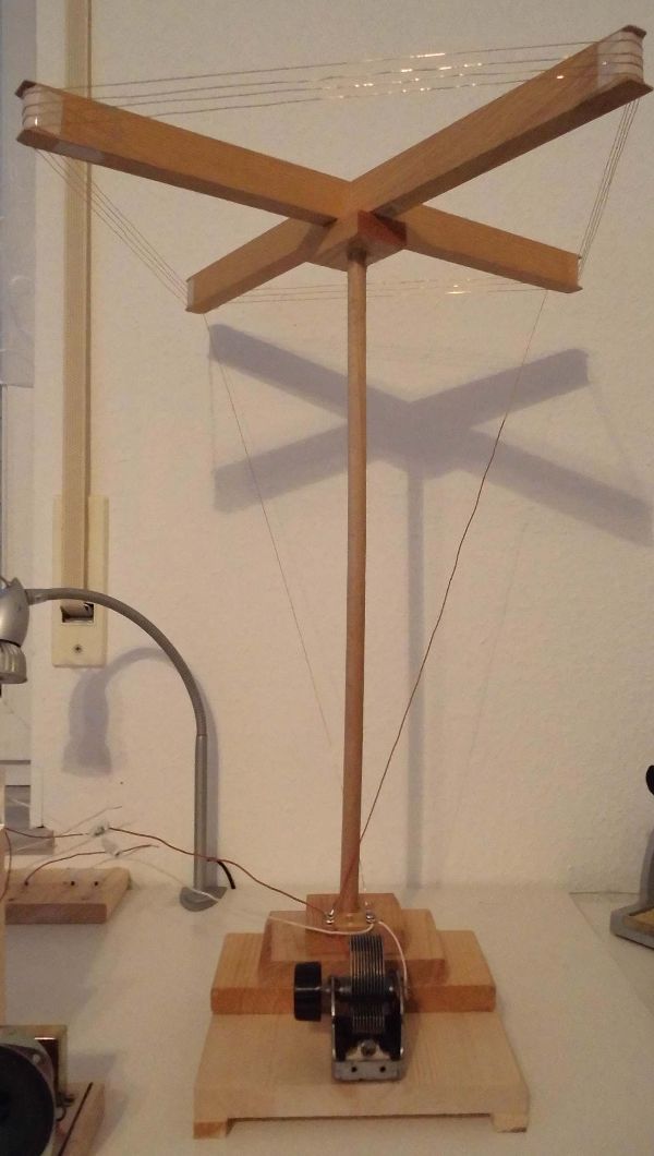
The following picture shows such a horizontally oriented tuned magnetic loop antenna that is being used with the receiver presented in the previous post. It is made of a wooden frame with 4 turns of copper wire around it (side length is 35cm). A 300pF variable capacitor in series with a 15pF capacitor is connected parallel to the loop and allows tuning from approximately 5800kHz to 6400kHz, covering the 49m shortwave band.
To thank the Author because you find the post helpful or well done.