AC/HL
? AC/HL

I have an early Mazda AC/HL with strange 5 pin base. The two short pins are the filament pins. The three long pins are for the anode, grid and cathode. But which pin is connected to what?


To thank the Author because you find the post helpful or well done.
unknown valve

I think it is not a Mazda but a Metropolitan-Vickers (Cosmos) valve. The base shows clearly the logo.
How to find out base connections:
Prereqisite: continuity at the filament pins.
Assumption: it is a triode.
I would start with a capacity measurement from one filament end against the three long pins, one after the other. The one showing the highest value is the cathode. Do not expect much difference: the f-k value may be only 3-4 pF higher than at f-g,
Valves of similar system size show e.g.8 pF at f-k; 5 pF at f-g; 4 pf at f-a
Now jumper the other two pins and connect a milliammeter from these pins (-!) to the cathode (+!).
Supply the heater from a controllable power supply. Start with 4 Volt and read the meter. If the valve is a 4 Volt type, it should develop an electron emission current of ca 0.1 to 0.3 mA. If there is no emission: carefully increase the heater supply. If possible, watch the cathode glow which must not become too bright. Light red to yellow is enough.
Now we have established emission, and the next step is to find out which pin is grid and which one is plate. Just disconnect one pin from the meter:
- if the current disappears, then the grid pin is open (the electrons build a cloud around the grid which blocks electrons from reaching the plate).
- if the current is maintained (maybe reduced), then the open pin is plate.
OK?
Good luck!
To thank the Author because you find the post helpful or well done.
just one measurement

Dear Peter
Sure you have an old fashion ohmmeter at hand.
After having heated up the tube (two short pins) you only have to search for minimum resistance at the three remaining pins.
The one at the negative lead of the meter indicates the cathode. The positive lead must be connected to the grid. The third pin left is, of course, the anode.
Best regards
To thank the Author because you find the post helpful or well done.
.

Judging by the illustrations in Keith Thrower's book on 1926-1946 valves, the anode is the one marked "A" on the base, the next pin clockwise is the cathode, and the third is the grid. It was after all made to plug into a standard valve socket.
To thank the Author because you find the post helpful or well done.
AC/HL
Yes there is a Metropolitan-Vickers logo on the base. But on top of the bulb is printed Mazda and AC/HL. The AC/HL is a 4 Volt indirect heated triode. The AC/HL base does not fit into a B4/B5 base, but there were adapters available. The pinout is shown below. The anode pin is indicated with an A on the base. Thanks for the info.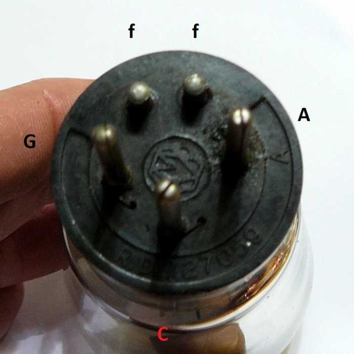
To thank the Author because you find the post helpful or well done.
AC/HL
Well, Metrovick activities went together with Mazda in the late 1920's. That is ok, no contradiction.
But the tube does fit in the B4 socket. Only a special (flat) contact adapter must have been provided to supply the indirect heater (short pins)
 .
.
I think that was another attempt to convert battery radios for wall plug operation.
Regards,
Kobi
To thank the Author because you find the post helpful or well done.
AC/HL
Konrad, Yes it fits in as you has drown. When the anode pin is put into the anode connection, it fits. I tried the two F and the G connection, but that does nor work.
Regards, Peter
To thank the Author because you find the post helpful or well done.