crosley: Ch= 1217; Prestotune 12: C16 Mystery
crosley: Ch= 1217; Prestotune 12: C16 Mystery

Hello dear collectors. I am restoring a Crosley Prestotune 12 (ch. 1217). While replacing capacitors, I came across C16, a 40 uF can which sits behind the 1st IF can and just to the left of the 6K6 oscillator. I found that it had already been snipped out of the circuit, so I don't know where the wires originally went (see circled part below):

Now here's the mystery. If you look at C16 (circled in red below) and trace its connections in both directions (yellow traces), you see that neither end is directly grounded. And yet my actual component has only one solder connector on it (ground being through the can to the chassis).

So I have a C16 that has to have one end grounded according to the actual radio I'm working on, but neither end is grounded according to the schematic. Is the schematic wrong? Am I wrong? Any ideas? Thanks very much!
To thank the Author because you find the post helpful or well done.
Perhaps you are really looking at C13

Hi Michelle,
Studying the schematic and parts list, it appears to me that C16 is a temperature compensating capacitor going to the grid of the oscillator tube. Neither end of that one is grounded, but it is also not a 40 uF electrolytic capacitor. It is probably a small value ceramic or mica capacitor (the parts list I have doesn't list a value for this particular part).
There are two 40 uF electrolytic capacitors in your radio -- C15, which is the first power supply filter (connected to 5Y3 filament) and C13 (connected to screen grids of three tubes -- two 6U7s and a 6A8). Both of these electrolytics are grounded to chassis on their negative terminals.
Since the original electrolytic has previously been snipped out of the circuit, the odds are that someone previously replaced it with a smaller tubular capacitor under the chassis. Check to see if there is a new electrolytic capacitor wired to where either C13 or C15 should be connected to the circuit. If it was replaced many years ago (which is very likely), you'll want to replace it again with a new electrolytic. You can wire your new replacement under the chassis (perhaps as was done for the previous replacement if there is one).
Many collectors like to leave the original dead electrolytic can in place (even though it should be disconnected from the circuit), since it is visible from the top of the chassis and would alter the appearance if removed. Others like to open up the old can and hide the new replacement inside it. I don't usually have the patience to do that, but it's a nice option for those that worry about the appearance under the chassis.
Best regards,
Tom
To thank the Author because you find the post helpful or well done.
Restoring capacitors

Dear Michele,
try to preserve the outer shape whenever possible, at least, if the component is visible. It is not as difficult as it appears. But you have to be patient. One possible procedure is shown below.
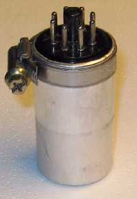
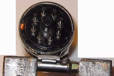
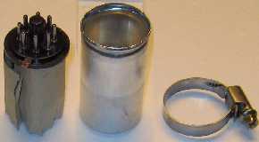
From Maurice (www.hamm.nl, I do not know him. But he had a look at this document on the RM website) I got the tip to use a gripper clamp to stabilize the upper part of the can while opening it with a small screwdriver. It works and is an improvement in comparison with the procedure I carried out, see Figures 4 and 5 ! The attached example is no electrolytic cap but an adapter for a crystal pick-up from a Danish radio, however, it is the same principle.
Good luck
Rolf
To thank the Author because you find the post helpful or well done.
Mystery Solved
Thomas, you are a true Wizard! You hit the nail right on the head. Thanks to your careful explanation, I can now see where I went wrong. C16 is indeed listed as a temperature compensating resistor in the parts list, however there is no value shown for it. The chassis bottom view that I have shows a can that really seems to be labeled C16. However, upon closer inspection, I can see that the "6" is really a "5". The print is very fuzzy and it's hard to tell if it's a 5 or 6. But now I understand that this is really the 40 uF electrolytic C15.
Both 40 uF electrolytics (C13 and C15) had indeed already been replaced by some previous owner, but not in their original positions. And C15 had been replaced with an incorrect 20 uF Atom. These electrolytics were leaking like a sieve so I am replacing them. There are a bunch of other smaller paper capacitors and these have also tested bad so they're going to be replaced too. Now I can go hunting for the real C16.
I think for this radio I will just bridge the new electrolytics under the chassis leaving the original cans in place but electrically disconnected. There is plenty of room in there and it is not really a very exotic radio. Note, however that for my DAF-1011 I am making extensive efforts to keep it as original looking as possible, including melting all the black gunk out of the block capacitors and hiding the new ones inside.
While I have your ear (your eye?), I found another problem here. Part no. 47 is listed as a 21 ohm 1/2 W. "flex" resistor. It looks like a 2 inch (5 cm.) long length of fabric insulated wire. Mine is broken in the middle. Can I just replace this with a conventional resistor? Why did they use this sort of resistive wire in the first place instead of an ordinary resistor? I've never seen anything like this before. Thanks! I very much appreciate your taking the time to look at the schematic and figuring out what I was doing wrong.
Thanks also goes to Rolf for some great photos of a can redo. That's a very clever idea to use a hose clamp that way. I'll have to remember this one.
To thank the Author because you find the post helpful or well done.
Flex resistor
Hi Michele,
Flex resistors were sometimes used for low resistance medium power resistors. This one is low enough wattage that they probably also could have used a carbon composition resistor instead. However, there is one other attribute of the flex-type resistors that the manufacturer may have intended: They function like a fuse, and will burn out without emitting a ton of smoke, if the current in the circuit is too high. A cabron comp resistor will also blow out, but not without making quite a stink first.
Note that resistor 47 is in series with the negative side of the B supply. The most negative point of the B supply is the center tap of the high voltage winding on the transformer. The negative side of the first filter capacitor 14 (correction to my comment above about 15 being the first filter cap) is connected there. From there, the route is through the speaker field coil, which serves a dual role as both a magnet for the speaker and a filter choke, and then through your resistor 47 before arriving at the chassis ground, where all the rest of the radio's circuitry is connected. Since there is a voltage drop across resistor 47 due to the B current flowing through it, the point where resistor 47 and the speaker field coil are joined is at a potential a few volts negative with respect to chassis ground. This negative DC voltage is used to set the grid bias on the output tubes, among other things.
If there is a short circuit in the radio that causes it to draw to much B current, your resistor 47 can blow out and act as a fuse to protect the transformer, rectifier tube, and other things. One very common situation that could cause resistor 47 to blow out would be a short in the second electrolytic filter cap 15.
You can replace resistor 47 with a modern metal film 47 ohm 1/2 watt resistor. If you put in one with a lot higher wattage, everything will work fine, but you will lose the fuse function that this resistor has.
Best regards,
Tom
To thank the Author because you find the post helpful or well done.
Flex resistors also usual in Germany in the 30ies

Flex resistors were usual in the 30ies. Look here samples from Germany which I found in "Handbuch der Funktechnik, vol 2, Franckh, 1935".
This types of resitors were comparatively small and easily maintained.

This one has a cord of asbestos with wound around of resitive wire. It has only low resitance values but is capable of a few watts power consumtion.
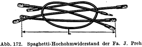
Also for higher resitance values such "Spaghetti" resistors were produced.
If such a cord resistor has to be replaced, indeed a normal resistor with appropriate wattage can be used.
Best Regards,
Dietmar
To thank the Author because you find the post helpful or well done.

Dear Michele,
just a warning!
Please, use great care in the handling and disposal of the flex resistor. 99% the fabric tissue is asbestos, very very dangerous if inhaled or in contact with the skin.
Best wishes for your radio, Emilio
To thank the Author because you find the post helpful or well done.
Flex resistor
Thank you, Thomas for such a clear explanation of both the history of flex resistors and the purpose of this one in this radio. Your description is so good I am printing it and keeping it with the schematic. I am certain that your theory on how this resistor broke is correct, given how badly the C15 was leaking. I will take your advice and replace it with a 1/2 W. metal film.
And thanks also to Dietmar for confirming the replacement and for those great photos of flex resistors. That is indeed exactly what mine looks like. I learned something new!
Finally, big thanks to Emilio for correctly pointing out the hazards of asbestos. You can never be too careful with that stuff. It is indeed very dangerous. This is one place I wouldn't have thought of looking for it, but now that he mentions it, I wouldn't doubt at all that this insulation is asbestos, especially given the application.
To thank the Author because you find the post helpful or well done.