De Emphasis Circuits on Non Armstrong Licensed Radios
? De Emphasis Circuits on Non Armstrong Licensed Radios

In calculating the de emphasis for 75 uS on the German export radios for North America, made by Telefunken and Braun, the circuits are adjusted at exactly 75 uS!
Telefunfen paid $250,000 to the estate of Armstrong in 1954 to use the FM patent license(Empire of the Air: The Men Who Made Radio), where as other German manufacturers (similar to RCA) waited to settle in the mid sixties for patent violations!
It has been observed that other German radio manufacturers designed de emphasis circuits for FM reception that are way below the European standard of 50 uS, relying on tone coloration to adjust for proper sound on FM.
The question arises, what are the tone coloration's effect on the AM, SW, tape playback, and phonograph circuits when one of them are put to use after the de emphasis circuit is adjusted to 50 uS or 75 uS, from the original manufacturers setting?
To thank the Author because you find the post helpful or well done.
De-emphasis on early FM radios

The "FM" modulation used for broadcasting indeed is a mixture of frequency modulation (below pre-emphasis corner frequency) and of phase modulation above this corner frequency.
- Audio frequency components below the corner frequency are transmitted as frequency modulation, and
- audio frequency components above the corner frequency are transmitted as phase modulation.
Phase and Frequency modulation are highly related, and therefore are named angle modulations. The reasons for this somewhat complicated "FM" modulation used for broadcasting is twofold.
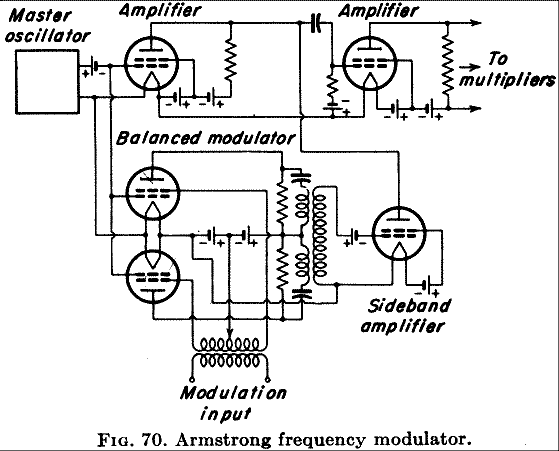
- Early broadcast "FM" transmitters indeed used phase modulators, consisting of a ring modulator, a 900 phase shift network for the carrier and an adder (Armstrong modulator). Only in this configuration it was then possible to stabilize the carrier frequency with a quartz.
- Receivers always used frequency demodulators. The reason for this is that phase demodulators do need a reference phase (additionally transmitted), whereas frequency demodulators have their reference frequency built in (LC circuit).
Frequency demodulators only match to phase modulators if an integrating network (de-emphasis) is following the frequency demodulator. However, integrating to very low frequencies is not possible without an active RC network (including an amplifier). That is why a pre- / de-emphasis corner frequency was chosen.
However, a frequency demodulation adds noise with ascending amplitude proportional to its frequency. A de-emphasis network is necessary that reduces the noise amplitude to a constant value, and so gets rid of hiss.
Nowadays FM transmitters use frequency modulators because frequency stabilization no longer is difficult, e.g. with a phase locked loop. These FM transmitters now have to use pre-emphasis networks.

So far to the complicated correlations between early TX and RX.
FM radio sets need a de-emphasis network. This ideally is concentrated in one RC lowpass filter as shown in the figure, and τ = RC being the time constant (τ = 75 μsec in region 2, and τ = 50 μsec in region 1).
However, concentrating the time constant in a single lowpass network demands an absolute flat frequency response of the rest of the receiver.
For early receivers this was by no means a matter of course. The de-emphasis had finally to fit at the loudspeaker. In such receivers various stray capacities (not shown in a schematic) contribute to the effective capacitance of the de-emphasis network.
If the time constant is calculated from the built in resistor R and condensor C, a too low value of the time constant will result. Further more, the effective value of the resistance often is affected by internal resistances of the discriminator/demodulator which has to be taken into account.
Later on, when FM tuners and FM stereo came up, the discriminator output had to be flat up to at least 53 KHz. The de-emphasis networks for left and right channel come after the stereo decoder. Here the time constants are concentrated within the RC lowpass filters. So the de-emphasis is correct at the interface between tuner and amplifier.
For early receivers with built in loudspeaker, no exact definition of an interface was available. Also disk recorders had no uniform features because piezo electric, ceramic, and magnetic picups were usual. And tape recorders had upper corner frequencies of 8 kHz, 15 kHz, and 22 kHz, depending on the model.
On these days a general standardization was missing for the audio interfaces. Therefore each vintage set has to be checked individually.
Regards,
Dietmar
To thank the Author because you find the post helpful or well done.
Armstrong Frequency Modulator

A principle schematic of an Armstrong frequency modulator is found in "Henney, K.: Radio Engineering Handbook, McGraw-Hill, 1959, P. 21-65"

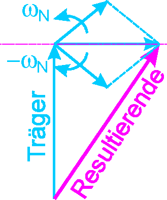
A balanced modulator gives a double sideband modulation with suppressed carrier (DSB_SC). The carrier amplifier has to serve a 900 phase shift, and is added to the DSB_SC.

From the vectors can be seen, that a phase modulation is realized only approximately. The approximations is sufficiently, if the phase deviation is very small. A bigger phase deviation and resulting also a greater frequency deviation is achieved with the aid of frequency multiplication.

Fig 1. from "Pender, H.; McIlwain, K.: Electrical Engineers' Handbook, Electric Communication and Electronics, 4th ed., Wiley, 1950, p. 8-11" shows a block diagram of an Armstrong FM TX.
The early FM radio sets are "matched" to these kind of FM transmitters without any audio processing as it is usual today.
Regards,
Dietmar
To thank the Author because you find the post helpful or well done.
? Negative Feedback Systems

"For early receivers this was by no means a matter of course. The de-emphasis had finally to fit at the loudspeaker. In such receivers various stray capacities (not shown in a schematic) contribute to the effective capacitance of the de-emphasis network."
I believe the more appropriate question is, why did some radio manufacturers export the same radio for region 2 (75 uS) that were designed for region 1 (50 uS)?
Did these manufactutrers believe that a tone coloration circuit would be able to accomodate the differences in sound?
Probably a more eventful discussion would be, negative feedback systems in radios, the pioneers who contributed, use, eventual demise, and possible use in present day design,
It should be understood, that the discussion of pre emphasis/de emphasis is in no way an attack of certain radio/amplifier design approaches that were used in the past. Rather, the intention here is to explore this whole area of history, how these designs were applied, and how they are applied with today's audio signal processing.
Many engineers involved in FM radio design and FM broadcasting in North America are not too familiar with negative feedback sytems that were used in radio design many years ago, and how it can be used to compliment a de emphasis circuit in creating a flat audio response.
Thank you
Omer
To thank the Author because you find the post helpful or well done.
"sound" is a matter of taste

The most famous book about negative feedback has been written in 1945 by "Hendrik w. Bode: Network Analysis and Feedback Amplifier Design, van Norstrand, 1945". Bode was with the Bell Telephone Laboratories (Bode diagram). Also a standard volume is the book from "John G. Truxal: Automatic Feedback Control System Synthesis, General Books LLC, 2010". Negative feedback is state of the art at least since Bode published his book. Why shouldn't "many engineers" not be familiar with this topic?
But the question goes much deeper and so an answer is not possible in general.
Indeed, the frequency response of an amplifier can be influenced by a frequency dependent negative feedback loop. This is greatly used in tube radios for tone control or psycho acoustics (loudness).
Whether to use a single loop or a concatenated loop is a matter of the makers philosophy, and some circuits are quite complicated. Probably a Spice simulation could give deeper insight.
But the makers were also competitors, and so how to get a "good sound" was a secret. Nearly none of the developping engineers is still alive and could be asked.
In the dawn of FM radio transmitters had a flat audio frequency response (together with a FM set with neutral tone control). But people then still liked the well known "full" AM sound, and so sophisticated tone controls were developed as a marketing feature.
However, all kinds of tone controls of the audio amplifier are not inherent part of the FM transmission, and so no part of Armstongs patents, unlike pre-emphasis and de-emphasis.
So your speculation "With all of these observations, we came to the conclusion that the elaborate circuits in the amplifier circuits on non licensed Armstrong radios were there, to go around patents and licenses, at the time, since transmission equipment was not that sophisticated in North America and hardly anybody listened to FM during the 1950's and 1960's." can be answered with "no".
Export FM models for region 2 had a de-emphasis of 75μsec. To convert an European model to an export model the de-emphasis had to be changed.
We look to the example you stressed. "Telefunken Gavotte 7 Export model has an extra 330pF (C39) on the de emphasis circuit than the German model. In doing calculations, we realized that the German model uses only 330 pFs but the American model uses two 330 pF capacitors in the de emphasis circuit. To further prove his point, we actually found a German model Gavotte 7 that didn't sound too good on many FM stations, added 330 pFs, and the radio sounded heavenly on FM!"
Both models have a de-emphasis lowpass with R=100kΩ and C with the value given above. If the time constant is calculated, the European model so had τ=33μsec, whereas the US model had τ=66μsec. However, some stray capacitance has to be taken into account. For the EU model this will be 17pF, and for the US model this will be 9pF. From the schematic alone the difference of the values of the stray capacitances can't be explained.
It's nice that you found a "heavenly sound" after correcting the de-emphasis. However, what does that mean? Sound clearly is a matter of taste, which can't be discussed. And very likely, some of the listeners will be not pleased with the nowadays Optimod compressed sound from many FM stations.
Regards,
Dietmar
To thank the Author because you find the post helpful or well done.
 Thread closed by a moderator. But replies can be made through a moderator.