philips: Dial lamp is not working Philips B3X95U radio
? philips: Dial lamp is not working Philips B3X95U radio

Dial lamp is not working on my recently recapped and working Philips B3X95U radio. The light was out prior to the recap, so I was expecting that I would need to replace it.
I found in the service manual that the lamp used is 8009 D-07. A cross reference I found online indicated this is a 6.3V .25A.
I have tried an E10 6V .2A LED and incandescent bulb both did not work. Measured the voltage at the lamp socket and it is reading 6V with no bulb and about 4V with the bulb in place.
I by passed the socket with jumpers to a known good socket / bulb and still does not work. I must be missing something?
If anyone can point me in a direction on what to check, I would appreciate any help you can provide.
Thanks
To thank the Author because you find the post helpful or well done.
philips: Dial lamp is not working Philips B3X95U radio

Hello James,
I think there is a misprint in the service documentation.
The heating circuit of your device has 100mA.
So a light like 8089D (12V / 0,1A) should be installed and not an 8009D (6.3V / 0.25A).
Like in this==> list.
Best Regards WB.
To thank the Author because you find the post helpful or well done.
philips: Dial lamp is not working Philips B3X95U radio
Hello Wolfgang,
Thanks for looking at the heating circuit and noting the 100mA. Since I am reading 6V at the light socket, would the 8006D (6.3V / 0,1A) be the correct bulb to try?
Best Regards, James
To thank the Author because you find the post helpful or well done.
philips: Dial lamp is not working Philips B3X95U radio

Hello James,
lamp type 8009 D-07 with 6.3V .25A is correct, as not only the the heater current runs through it, but the entire current of the set.
I wonder, why the 6.3V bulb doesn't show a dim glow when the voltage is 4V if the bulb is in place.
The full brightness should appear, once the tubes are heated up and the radio is working.
Jacob
To thank the Author because you find the post helpful or well done.
philips: Dial lamp is not working Philips B3X95U radio
I am still new to restoring tube sets (this is my 3rd) and I am still learning. The bulbs that I have tested on this unit are E10 6V .2A, both LED and incandescent.
I tested them in a new socket on my DC power supply and they both work from 6-12V. I attached the same bulb/socket using jumpers to the -/+ on the top of the existing socket board and it does not work. I have also tried with them screwed into the existing socket.
I have tried both existing socket and jumper socket with the room lights out to check if there is any glow from the incandescent bulb and there is nothing.
The bulb is connecting to UY42 tube which appears to have .1A. So based on Wolfgang’s suggesting that it might be an error in the service manual, that might explain why the .2A bulb was not working? Would you expect that the 6V/.2A incandescent bulb would have some glow even at 6V / .1A?
The bulb the manual suggests is 6.3V /.25A, can that be correct if the source is .1A?
Seems that a .1A bulb E10 6V is hard to find in the US. Any suggestions on possible alternatives?
To thank the Author because you find the post helpful or well done.
philips: Dial lamp is not working Philips B3X95U radio
I don't know if it is useful information for US conditions, but in Sweden, 6 V 0.1 A (usually marked 6 V 0.6 W) E10 bulbs were common for bicycle rear lights until early 1970's. Later on, new legislation required 3 W bulbs in the rear lights.
To thank the Author because you find the post helpful or well done.
philips: Dial lamp is not working Philips B3X95U radio
Hello James,
Jakob is right, but I thought that the lamp on your model was connected in series with the heater.
I assume you are running your device on 120 volts.
Two questions:
Is your radio working and the problem is only the light?
When you remove the light, the N.T.C. R13 is hot, which is connected in parallel to the lamp?
I think something is interconnected in your device.
Even if a lamp with 6V / 0.25 A is connected in a 100mA circuit, it must glow weakly.
See picture:

To thank the Author because you find the post helpful or well done.
philips: Dial lamp is not working Philips B3X95U radio
Well, that is a great question! I thought it was working as I powered it up on my dim bulb to test it prior to ordering the capacitors. It played, but with some distortion and hum. I “assumed” this was due to bad caps, which did test way out of spec. However, since you asked that question it made me realize that I did not take all the measurements and observations I should have before I replaced the capacitors.
The radio plays AM and both SW, I can pick up stations on both. Of courses its hard to say if it sounds ok since the source is not great. One of the key features that interested me in this radio is the PU button. I like to plug in a Bluetooth source to get a clean single. On the PU I get a lot of hum and seems to be ground issue, as it will get louder if I touch the cord. Now I have read that with radios like this with no transformers that you should not use the PU as there is risk of it being hot.
I have now gone through and tested all the resistors and found two that were way out of spec:
- R3 was at 63K should be 5.6K. I replaced it with two resistors in series to get it to 4.3K as a temporary test to get closer to spec.
- R8 was at 800K should be 470K. I replaced with a 330K as a temporary test to get closer to spec.
- The NTC R13 READS AT 3 OHMS, but I read you cant really test this part.
- The voltages at the light socket are:
- 120V AC with bulb
- 9V AC with no bulb
I have attached my voltage measurements using the debug notes posted by Jean de Bellefeuille with my readings in red. I am not clear if his note indicates what I should expect to see, but my voltages are way off from his notes.
Maybe this indicates a bad tube?
Any guidance you can provide would be greatly appreciated. Let me know if you have any questions.
Since replacing the bad resistors, there is no noticeable difference as I still have no light and still have the same hum on the PU input.
Any thoughts about using the PU input with a Bluetooth source, is this a risk? Any recommendations for modifying the circuit to make it safe?
Attachments:To thank the Author because you find the post helpful or well done.
philips: Dial lamp is not working Philips B3X95U radio
Disregard the comment about the transformer, it obviously does have a transformer. I had read a thread online about it not having one and did not recognize it since it is so small compared to the others I have worked on. As I said, I am still learning… I see it clearly on the schematic and of course should have checked it when doing my measurements. Transformer voltage is 133V DC as noted on the previous attachment.
To thank the Author because you find the post helpful or well done.
philips: Dial lamp is not working Philips B3X95U radio
Ok, after further study, it appears the small transformer is the audio ouput transformer, is that correct? So is this a “transformerless” radio with a hot chassis? Should I not use the PU input?
To thank the Author because you find the post helpful or well done.
philips: Dial lamp is not working Philips B3X95U radio
Hello James,
yes, this radio is “transformerless” with a hot chassis, I'm discouraging to use the PU input, as this is dangerous.
You should use an AM- micro- transmitter to get your Bluetooth- signal to the radio, where you can receive it as a normal radio station.
As there is no current limiter or a soft starter to cut the high inrush current of the heater circuit, it's rather impossible to operate a dial lamp successfuly as specified in the diagram.
The dial lamp should be disconnected from the existing circuit. Then you should take a dial lamp that can operate directly at the 120 v line voltage or via a dropping resistor or a dropping capacitor. To proceed you should ask an experienced radio restorer in your area.
Jacob
To thank the Author because you find the post helpful or well done.
philips: Dial lamp is not working Philips B3X95U radio
Thanks for confirming the PU should not be used. I will investigate alternatives for Bluetooth input.
So, I am understanding you correctly, are you saying the lamp issue is a design flaw? I assume it did work during the life of the radio. Is it just a bad design in that the bulb will fail prematurely due to the inrush current? So the stated bulb in the service manual is incorrect as the 8009 D-07 6.3V .25A, it would never have worked at 120V, correct?
I appreciate your recommendation to consult with an experience restorer in my area. This is a learning process for me, so I am determined to work through the issues and learn more with each unit I restore.
I will look in to a 120V capable LED bulb to fit the E10 socket. When you say disconnect from existing circuit, you mean to disconnect the NTC R13? If you connect a 120V capable LED bulb directly to the 120V and power switch, it will turn on and off with the radio, correct? I understand the NTC is there so that the radio would operate if the bulb is out. So with this modification, what happens when the bulb fails? Radio does not turn on?
To thank the Author because you find the post helpful or well done.
philips: Dial lamp is not working Philips B3X95U radio
Indicator light and PU input questions aside, I have some questions related to my voltage readings. My voltages are consistently low.
I have attached a marked-up schematic with my voltage measurements.
Any feedback on this would be very much appreciated.
Attachments:
To thank the Author because you find the post helpful or well done.
philips: Dial lamp is not working Philips B3X95U radio
The voltage readings in the schematic are valid when the radio is supplied from a 220 V AC mains. At 120 V supply, all voltages will naturally become much lower.
Regarding safety issues for the PU input, you will not need to worry if the isolation capacitors C33-C34 are in good order. If you are going to replace them with modern capacitors, make sure that they have an Y2 approval. A better solution for the PU input, which was used in some more expensive AC/DC radios, was an isolation transformer instead of the capacitors. This would eliminate the inherent hum problems and also give a bit better bass reproduction.
To thank the Author because you find the post helpful or well done.
philips: Dial lamp should work
Hi James and colleagues,
I'd like to cut in at this point, as I've been following this thread for some time.
James, to your last post: The DC voltage is probably given for 220 V operation (switch open). The plate voltage is lower for reduced mains voltage - I see Torbjörn being faster. Did you notice that voltages at the UF 89 are high in spite of that? This tube is probably weak.
But what with the lamp? Jakob is right that it is operated by heater AND plate current. Thus a 250 mA type should be correct. Jakob, this is also the solution for the inrush current. At this time there is no plate current, and this will enable the lamp to take up the pulse. I can't imagine Philips to sell a set that has a flaw like that.
Now, what happens without lamp? There is no current path except for the NTC. Thus it heats up, takes on low resistance and thus enables the set to work in a kind of emergency mode. That's its only purpose.
Your radio playing proves this part is either ok or shorted.
You should measure:
- Cold resistance of the NTC, to be in several 100 ohms range
- Voltage across its terminals (not to ground) when the set is playing. This should be around 10 volts.
Regards,
Steffen
To thank the Author because you find the post helpful or well done.
philips: Dial lamp should work
The voltages at UF89 are probably strongly dependent on AGC action - if the radio is receiving a strong signal, the tube will operate near cut-off with low anode and screen currents, and hence a low voltage drop across the series resistors and fairly high voltage from the respective electrodes to ground.
Also, it might be possible that the voltage readings in the schematic are taken with an old low-impedance multimeter which loads the circuits more heavily than a modern DMM with maybe 10 Mohms of inner resistance.
To thank the Author because you find the post helpful or well done.
philips: Dial lamp should work
Thanks for all the great feedback. I suspected the low voltages might have something to do with the line input being 120 vs 220 as shown on the schematic.
I did notice that the UF89 was the only one that showed higher voltage. Based on Torbjörn comment that the original measurements were made with a analog volt meter and that a strong signal might also impact the voltages, I took some measurements with a vintage Simpson 260 volt meter I have. Here is what I found:
Pin 7 went from 81.5V on my DMM to 65V on the Simpson 260
Pin 8 when from 85V on my DMM to 70V on the Simpson 260
Tuning in to weaker signal or switching to the PU input did not seem to make a difference
Is there any reason that I should consider replacing the UF89? Or is this normal
On the indicator light:
Cold resistance of the NTC is: 3 Ohms
Voltage across its terminals (not to ground) is: .6V AC
Dose this indicate that the NCT is bad? If so, any recommendations on what to replace it with?
To thank the Author because you find the post helpful or well done.
philips: Dial lamp should work
Hello James,
the cold resistance of the NTC is approx. 9.500 Ohms.
The hot resistance of the NTC is approx. 220 Ohms.
The NTC is only required if the lamp is defective in order to bypass it. Unsolder the NTC on one side and see whether the lamp lights up.
One more thing, Philips has certainly not produced any devices in which the lamp is endangered by the inrush current.
Regards WB.
To thank the Author because you find the post helpful or well done.
philips: Dial lamp should work
Hello Wolfgang,
The cold resistance of the NTC is approx. 3 Ohms.
The hot resistance of the NTC is approx. 0 Ohms.
I removed one leg and the light did light for about 1 second. Now that light is dead.. This was and led that is rated at 6V .2A. Same value incandescent bulb did not appear to light, also dead.
I did also test the NTC by measuring the Ohms while I heated it with my solder iron on the lead. It drops from 3 Ohms to 0 Ohms in about 10 seconds.
Dose this indicate that the NCT is bad? If so, any recommendations on what to replace it with?
I am still confused about the correct bulb voltage. If there is 120V at the socket, how can a 6V .2A bulb be correct?
Thanks for your help!
James
To thank the Author because you find the post helpful or well done.
philips: Dial lamp is not working Philips B3X95U radio
Hello Torbjörn,
I wanted to ask about your comment related to using a isolation transformer instead of the capacitors. This is an interesting idea, to provide a safe and clean signal input.
I did some searching to see if I could find any previous threads that discussed this as a modification / upgrade for hot chassis PU inputs but did not find much. Have you done this in the past? Any idea about the value of the transformer that would be needed?
Thanks,
James
To thank the Author because you find the post helpful or well done.
philips: Dial lamp is not working Philips B3X95U radio
Hi,
i just checked the cold resistance of all tubes and found values as follows:
UBC81: 21 Ω
UCH81: 28 Ω
UF89: 20 Ω
UL84: 65 Ω
UY41: 47 Ω
Dial lamp: 2 Ω
this results in a total resistance of 183 Ω .
At 120 V line voltage, this results in an inrush current of 0.66 A.
The question arises how often a 0.25 A dial lamp can withstand this current, probably not very often.
The situation looks much better when operating the radio at 220 V as there is another resistor (R11) of 950 Ω in the heater circuit.
The total resistance is then 1133 Ω. The inrush current is then only 0.194 A, which is a gentle operation for the 0.25 A lamp, where it will last forever.
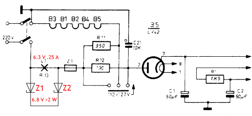
With only 3 Ω the NTC seems to be defective. You could replace it with 2 Zener diodes, each 6.8 V, anti-serially connected. They should be at least 2-watt types, maybe better ones are 4 - 5 watt-types.
This also will solve the problem of the high inrush current for the bulb.
Jacob
To thank the Author because you find the post helpful or well done.
philips: Dial lamp is not working Philips B3X95U radio
Hi Jacob,
Thanks for looking at that and providing the explanation. Interesting, I bet many units in the US were upgraded in some way like this over time to compensate for this. Or like mine the bulb has been out for many years.
I could live with the bulb being out, but I wanted to understand what was going on with it and fix it if possible. Your solution look’s viable and easy to implement. I will investigate some Zener diodes for my next parts order. Thanks again for the feedback! James
To thank the Author because you find the post helpful or well done.
philips: Dial lamp should work
Regarding the comment on the UF89 voltages, does anyone have feedback about this?
"I did notice that the UF89 was the only one that showed higher voltage. Based on Torbjörn comment that the original measurements were made with a analog volt meter and that a strong signal might also impact the voltages, I took some measurements with a vintage Simpson 260 volt meter I have. Here is what I found:
Pin 7 went from 81.5V on my DMM to 65V on the Simpson 260
Pin 8 when from 85V on my DMM to 70V on the Simpson 260
Tuning in to weaker signal or switching to the PU input did not seem to make a difference
Is there any reason that I should consider replacing the UF89? Or is this normal"
To thank the Author because you find the post helpful or well done.
philips: Dial lamp should work
Hello James,
One more thing, you wrote: I have tried an E10 6V .2A LED.
But LED´s only work with direct voltage (DC) and not with alternating voltage (AC) with which you operate the device.
Can you take a picture of your NTC, this is mysterious with the low value of NTC cold 3 Ohms.
Regards WB.
To thank the Author because you find the post helpful or well done.
philips: Dial lamp should work

Hi James,
both voltages at Pin 7 (Anode) and Pin 8 (g2) should be nearly the same measured by a DMM.
Make sure that resistor R3 and R22 are correct. You can measure (without connected to mains !) directly in the circuit because they are both connected to the tube.
Depending on strong or weak signals the voltage at pin 2 (g1) should variate and thus the anode voltage (pin 7) should change. However, capacitor C 7 may have some leakage which has a strong impact on the automatic volume control (AVC) voltage due to the high resistance of R 4. So you should test the leakage of C 7.
However, the AVC in such small sets is sometimes not very effective.
Best regards
Rüdiger Walz
To thank the Author because you find the post helpful or well done.
philips: Dial lamp is not working Philips B3X95U radio
Hi James,
since the current for the dial lamp is asymmetrical due to the half-wave rectification, Z- diodes of different voltages can be advantageous for the correct brightness of the lamp, e.g. 4.7 V for Z1 and 8.2 V or 10 V for Z2. It may also be possible to use Z2 alone without Z1.
The lamp should never light brighter as if operated at its rated voltage.
You need to find out what is best, I can't make more predictions.
Jacob
To thank the Author because you find the post helpful or well done.
philips: Dial lamp should work
Yes, you are correct on the LED bulb being DC. I did also try an incandescent bulb of the same value that should have worked on AC.
Here is a picture of the 3 Ohm reading on the NTC R13 with no bulb.
- NTC R13 (208 KB)
To thank the Author because you find the post helpful or well done.
philips: Dial lamp is not working Philips B3X95U radio
Hello Jacob,
I will buy a variety of Zener diode values and test which combination works best. You mention the light should not be brighter than it would be at its rated voltage. So I would be testing different combinations of Z1/Z2 or just Z2 , then measuring the voltage to get close to 6.3V and then checking the brightness. I would assume I can check the brightness compared to the bulb operated at the correct voltage on my power supply. Is this the approach you would suggest?
To thank the Author because you find the post helpful or well done.
philips: Dial lamp should work
Hi Rüdiger,
I checked C7 and it is good. However, you mention R3 and that is one that was bad (reading 64K). I replaced it with two resistors in series to get it to 4.3K as a temporary test to get closer to spec. This is what the current voltage measurements were based on. So, once I have the correct 5.6K resistor in place I will measure again.
I also had a bad resistor at R8 (reading 800k), should be 470K. I replaced with a 330K as a temporary test to get closer to spec. I will be replacing this as well and will update my voltage measurements.
Thanks,
James
To thank the Author because you find the post helpful or well done.
philips: Dial lamp should work
Hallo James,
for me the resistance in your photo is not an NTC.
This is a completely normal resistor with 3 ohms.
Colors orange, black, gold, silver result in 3Ω / 10% tolerance
This resistor was probably soldered in earlier instead of the NTC.
Resistor NTC
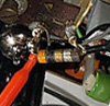

An NTC looks like the one in my picture in Post 7.
Regards WB.
To thank the Author because you find the post helpful or well done.
philips: Dial lamp is not working Philips B3X95U radio
Hello James,
its OK with your approach, but don't rely much to the voltage across the lamp in the radio, as this voltage is distorted and unbalanced, so the multimeter may show wrong values.
You can compare the brightness of the lamp with an exactly identical lamp operated at 6.3V from your power supply.
It is helpful to look for the same yellowish glow of the two bulbs. Of course you can operate the bulb at lower brightness, if it is sufficient.
Jacob
To thank the Author because you find the post helpful or well done.
philips: Dial lamp should work
Hello Wolfgang,
Thank you for asking for the picture… they say a picture is worth a thousand words!
Sorry that I did not recognize this as a resistor. Seems obvious now that you point it out.
So do you think the light ever worked with the 3 Ohm resistor? Was it so they could use a lower voltage bulb?
I think I will try the Zener diode solution that Jacob has suggested. If that works, I will report back with detail on the parts used and a PICTURE!
Many thanks for all the help!
James
To thank the Author because you find the post helpful or well done.
philips: Dial lamp should work
Hello James,
no, it couldn't work with the 3 ohm resistor.
The heating voltage of the tubes without the lamp is 121.6 volts, just right for 120 volts.
But there is a much simpler solution.
Connect a MP capacitor with 2.2µF (Test voltage higher than 300Volt) in series with a 6.3V/0.1A lamp as in the sketch below.
This requires a small circuit change, but is definitely the cheapest solution.
For other lamps it has to be recalculated.
Diese Werte gelten für 120Volt~, 60 Hertz.

To thank the Author because you find the post helpful or well done.
philips: Dial lamp should work
Hello Wolfgang,
Thanks for providing this concept with the drawing, it seems easy to implement. Based on your drawing, it looks like I would Just remove R13 from the circuit, add the capacitor in front of L1 (in line on the black wire with 120v). Is this correct? See attached photoshop mockup picture of where I think this capacitor could be placed.
I was able to locate part number MKP4G042206F00KYSD Mfr.:WIMA Film Capacitors 400V 2.2uF 10% and will put this on my next order.
Let me know if this looks good.
Thanks,
James
Attachments:- Lamp Circuit Modification 2.2uF Cap (213 KB)
To thank the Author because you find the post helpful or well done.
philips: Dial lamp is not working Philips B3X95U radio
Hi Torbjörn,
I was doing a bit more research on the options for modifying the PU input to have a safer and cleaner circuit. I found and article from a few years ago written by Bill Reeves that outlines a few different options for doing exactly this. Attached is the drawing from the article for a simple option for a radio like this Philips.
I have also attached the schematic for the B3x95U marked up to show where I think I would connect this new isolation circuit to this radio. I would love to get feedback from anyone interested on this topic. The isolation transformer he used does not seem to be available any longer. I found this inexpensive one available on Amazon:
Model: EI14
AC impedance : EI14 600 : 600 Ohm
Item : Audio transformer
inductance : 290mH (±20%)
DC resistance : 135(±%)
Windability : Double-wire winding
Quality &wire diameter : QA-1 0.06MM
Primary coils : 800 turns
secondary coils : 800 turns
Alternating-current impedance value : 600
I am not sure it’s a good match to the one Bill recommended TY300PR(see attached).
Can anyone provide feedback on which transformer options I might consider and how best to connect this in this radios input circuit, I would really appreciate it. I want this to work with the PU button, so this seems like it would work with that.
I would still need to work out where I might be able to fit it in the radio and if I might replace the banana jack with a 3.5mm mono jack. Another option might be to just include a Bluetooth receiver pcb with this input circuit so there is no external connection needed.
Thanks,
James
Attachments:- Audio_Transformers_Ty300PR (284 KB)
- Audio Input Isolation Mixing Circuit to PU Input B3X95U (223 KB)
To thank the Author because you find the post helpful or well done.
philips: Dial lamp should work
Hello James,
You'll need to rebuild the circuit like I drew this.
The lamp gets a new circuit to the capacitor from the mains switch contact, which goes to ground.
The contact after the lamp is connected after the fuse.
The fuse is connected directly to the power switch.
Regards WB.
To thank the Author because you find the post helpful or well done.
philips: Dial lamp is not working Philips B3X95U radio
Hello,
my idea was to leave the existing circuit as it is, by only substituting the NTC- resistor by one or two Z- diodes.
However Wolfgang has suggested another solution with an extra circuit, operating the dial lamp via a dropping capacitor direct from the 120 V line voltage.
This capacitor must be rated for at least 120 V AC 60 Hz.
Jacob
To thank the Author because you find the post helpful or well done.