"Fremodyne" Superrgenerative Detector
"Fremodyne" Superrgenerative Detector

The Fremodyne was an early FM superregenerative detector. Usually, superregenerative detectors like this example operate directly at the receiving frequency. The Fremodyne uses an IF instead.
In "Ghirardi, A.A.: Radio and Television, Receiver Circuitry and Operation, Rinehart & Co, Inc., 1951" the Fremodyne is described as follows.
6-17. The "Fremodyne" Superregenerative Detector
The Fremodyne detector is of technical interest because of its versatility and compactness, although it has not been widely used. In a single stage (with a dual triode tube) it provides a local oscillator, a mixer, i-f amplification, and demodulation with a strong a-f signal output. For this reason, the Fremodyne circuit has been used mainly in some small, compact, and inexpensive receivers using only two or three tubes for FM reception.

Fig. 6-22 The circuit of the Fremodyne superregenerative FM detector. This versatile circuit performs the functions of local oscillator, mixer, i-f ampfifier, and demodulator. Its advantages are most important in compact, inexpensive FM receiver models.
The Fremodyne type of circuit is illustrated in Fig. 6-22. Since this is the first instance of the use of the superregenerative circuit in home receivers, a short digression for explanation of this system is in order.
The old regenerative type of detector was made quite sensitive by tuning the circuit near the point of oscillation to get the greatest amount of regeneration and resulting sensitivity. However, at a point very near oscillation, the circuit becomes very unstable so maximum sensitivity can not be obtained without the danger of oscillation. In a superregenerative receiver, the circuit is passed in and out of r-f oscillation at a supersonic frequency, called the quench frequency. No appreciable amount of oscillation at radio frequency gets started but the sensitivity is increased tremendously by the fact that the average operation is taking place at the sensitive oscillation point.
Now refer to Fig. 6-22. The incoming signal is fed to L1-C1 which is tuned to the r-f frequency, thence to the grid of V1. Meanwhile oscillator circuit and tube V2 supply an oscillator signal which is also applied to the grid of V1. The two signals are mixed in V1 in the same manner as the mixing occurs in any superheterodyne receiver. The difference signal, 22 mc, appears across L2 in the plate circuit and is the i-f signal of the receiver. Meanwhile, the output circuit is connected to form a Colpitts superregenerative detector, which demodulates the 22-mc i-f signal. The a-f modulation signal appears across R5 and is fed to the first a-f amplifier stage. The output signal is often strong enough to drive a power amplifier stage directly.
Regards,
Dietmar
To thank the Author because you find the post helpful or well done.
Interesting: I've never heard about Fremodyne. Surfing the net I've found this site with some examples of Fremodyne radios: http://www.users.bigpond.com/cool386/
I have not yet found any Italian fremodyne receiver
Best regards
To thank the Author because you find the post helpful or well done.
'Fremodyne' - My Implementation

This article and a challenge from my local parts supplier to make a one-valve FM radio sparked my interest. I built the set around an ECC84 valve.
The sensitivity is quite good, but the audio output is very low. Tuning doesn't work the way I expected - it seems to tune exactly like any other FM tuner, not the way a slope detector tunes at all. Even has a lod hiss between stations.
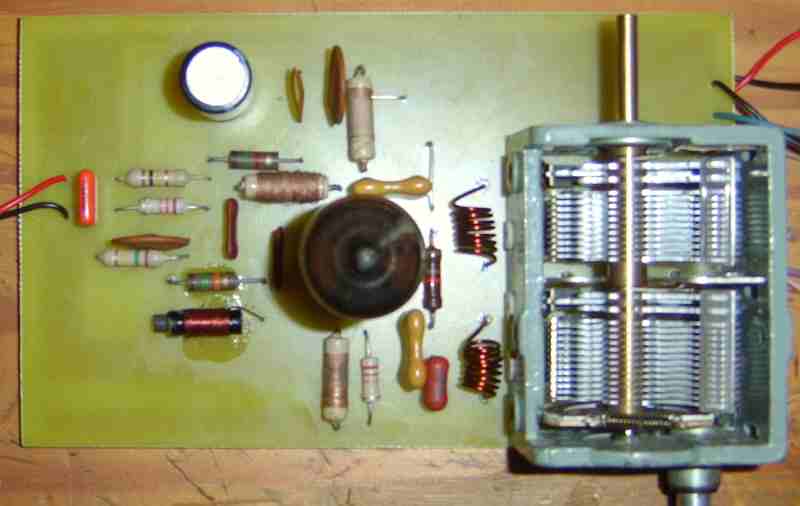
Normally, I hand-wire my one-valve radios, but this seemed a bit messy, so I designed a PC Board.
Here are some photos (Also have a .wav file, but don't know how to attach it.)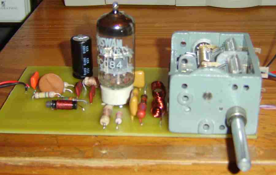
To thank the Author because you find the post helpful or well done.
More on Fremodyne
More about Fremodyne can be found at an Australian Site. [Link entfernt, da diese Seite nicht mehr besteht.]
Regards,
Dietmar
To thank the Author because you find the post helpful or well done.
Fremodyne Results
I performed a frequency scan of the Fremodyne using a program called pcrscope and a PCR-1000 receiver. Alas, this is a bit crude compared to using a spectrum analyser, but I hope it will give some insight into this interesting circuit
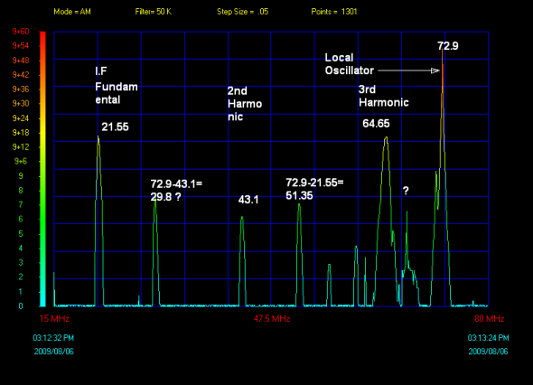
The ?s indicate areas of uncertainty. The set was tuned to 94.7 FM.
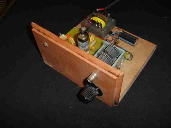
Also a picture of the finished set.
Alas, I still don't know how to attach a sound file to a post. Perhaps someone can help me with this (if its possible!). It sounds OK played through a Mullard 3-3 amplifier, not as good as more conventional tuners, perhaps.
To thank the Author because you find the post helpful or well done.