Graphite Anode Tubes with Isolated Getter Trap
Graphite Anode Tubes with Isolated Getter Trap

From Radio May 1946, Page 6.
Graphite Anode Tubes with Isolated Getter Trap
Graphite anode tubes have been limited to relatively few types in past years, due to manufacturing difficulties of degassifying an anode of such great mass, and the consequent high cost of manufacture. Heavy getter deposits upon the tube bulb have also constituted a barrier to the black body heat-dissipating qualities of graphite.
Crystal-clear glass bulbs have been realized through the agency of the isolated getter trap, developed by United Electronics Co. engineers. It is reported that the development makes possible graphite-anode tubes capable of dissipating large quantities of heat and improving operation on very high frequencies.
The radiating emissivity of graphite is 94% of black body. Its thermal conductivity is 1.92, and it is noted that high thermal conductivity permits rapid and uniform distribution of heat which avoids hot spots and consequent warping or fusing of tube elements. At average tube ratings, the normal operating temperature of graphite is 500° to 600° C. Graphite itself has no melting point. being infusible.
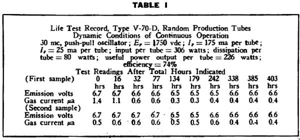
High-frequency operation of tubes requires constant inter-element spacings to achieve uniformity of tube and circuit response. It is stated that graphite anodes are accordingly well adapted to high-frequency operation, graphite being run at comparatively low temperatures and with little color. The independent gettering agent is designed to function at all temperatures. It is reported that graphite anode tubes with the isolated getter trap have an initial gas content usually under one microampere and that the tube becomes harder over several hundred hours of operation. Filament emission likewise improves.
Tabulation of readings as reported by engineers of United Electronics Co. for life tests conducted on the V-70-D tube with 612 watts continuous input at 30 Mc is shown in Table I. Emission improvement is shown as the emission voltage reading is reduced; that is, the lower the emission voltage reading, the better the emission.
These life tests represent operation in excess of ratings, the V-70-D being rated for 300 watts maximum input ICAS, and the tests being made at 306 watts continuous input.
United Electronics engineers predict revolutionary new conceptions of graphite-anode applications and revised viewpoints among tube users who in the past have not given much thought to the use of graphite-anode tubes for operation at frequencies above 100 Mc.
To thank the Author because you find the post helpful or well done.