Hewlett-Packard: 5306A (5306 A); Multimeter / Counter
Hewlett-Packard: 5306A (5306 A); Multimeter / Counter

Unfortunately my 5306A Multimeter/Counter with the measuring System 5300B shows only zeros ... I would be grateful if somebody can upload schematics ...
But here what I found published in the Hewlett-Packard Journal from June 1973 on page 7 to 15: HP published it and therefore there should not be a problem to publish this tied to the instrument.
DMM and DAC Modules Expand Low-Cost
Measuring System
A five-digit multimeter/ counter module and a three-digit digital-to-analog converter module are new members of the 5300 Measuring System joining the mainframe, battery pack, and four timer/counter modules previously available.
by James F. Horner, Lewis W. Masters, and P. Thomas Mingle
Altough basically a counting system, the 5300 Measuring System, as its name implies, isn't limited to counter measurements. The 5300A mainframe, with its six-digit 10 MHz counter, counts a signal presented to it by the snap-on functional module, which contains circuits for function selection and signal shaping. Therefore, any quantity that can be converted to an appropriate frequency by a snap-on module can be measured by the mainframe.
The first four snap-on modules were designed for counter-timer measurements. The newest, Model 5306A Multimeter/Counter (Fig. 1), is the first to apply the inherent flexibility of the mainframe to other types of measurements. It offers functions of dc volts, ac volts, ohms, and frequency, all the functions usually found in digital multimeters plus an extra one, frequency.
Another new module, Model 5311A Digital-to-Analog Converter, fits between the mainframe and the snap-on functional module. It converts any three digits of the 5300A display to a proportional analog voltage output. It can be used with any snap-on module, and with or without the 5310A Battery Pack, which is also an "in-between" module. The design of Model 5311A is described on page 11.
Four-Digit Accuracy, Five-Digit Resolution
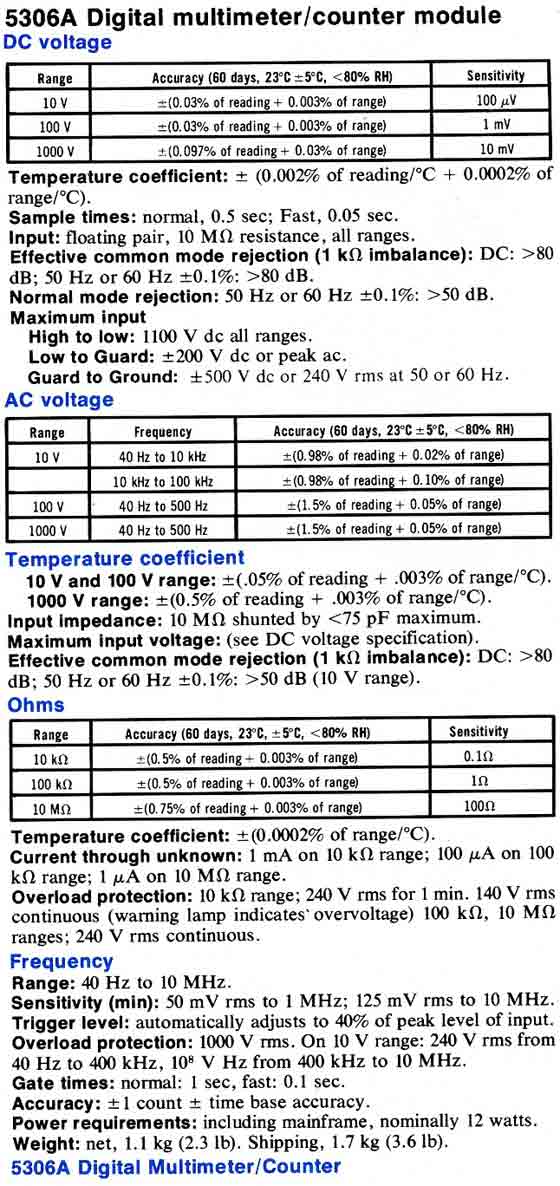
Model 5306A Multimeter/Counter measures dc voltage in three ranges: ±10 V, ±100 V, and ±1000 V full scale. Ac voltage is measured in ranges of 10 V, 100 V, and 1000 V, and resistance-measurement ranges are 10 kO, 100 kO, and 10 MO full scale.
Accuracy specifications are essentially those of a four-digit multimeter. However, for reasons to be explained later, Model 5306A's fifth digit is a full digit, not just an overrange digit, so measurement resolution and dynamic range are those of a five-digit instrument. The effect is to make every range on the 5306A equivalent to two ranges on a typical four-digit meter. For example, in the 100 V range the resolution is 1 mV, so measurements can be made from millivolts to 100 V without changing ranges.
When maximum resolution isn't needed and more than two measurements per second are desirable -- for example, when displaying the results of a coarse adjustment --- a FAST sample mode can be selected. Measurements are then ten times faster. Accuracy and resolution are both four digits.
In frequency measurements, the 5306A has the full six-digit accuracy and resolution built into the 5300A mainframe. Frequency range is 40 Hz to 10 MHz. The FAST sample mode can also be used for frequency measurements, again with one less digit of resolution.

Fig. 1
Two new modules tor the 5300 Measuring System are Model 5306A Multimeter/ Counter (bottom module of instrument in foreground) and Model 5311A Digital-to-Analog Converter (center module). The Multimeter/Counter measures dc voltag, ac voltage, resistance, and frequency. Other elements of the system are the mainframe (top module) four counter/timer modules and a battery pack.
Design Philosophy
In designing a four-digit multimeter snap-on functional module for a six-digit counter mainframe, many questions had to be answered. The most obvious was what to do with the extra two digits in the mainframe.
One digit was easy to dispose of. The designers of the mainframe had foreseen that some future module might require a polarity indication in the display, and had made it easy to generate a minus sign in place of the most significant digit. The 5306A uses the minus sign for dc voltage measurements.
The next most significant digit could have been used as an overrange digit, like the 1/2 digit of a 4 1/2 digit multimeter. But this would have been wasteful because a full digit (that is, 0 through 9 instead of just 0 or 1) could be displayed in that position. It was suggested that the 5306A might be designed with five-digit accuracy. However, the extra cost wasn't compatible with the concept of the 5300 Measuring System as a low-cost laboratory and field instrument. The accuracy specification was finally fixed at 0.03 %, or +/- 3 counts error in the fourth significant digit.
Percent of Reading versus Percent of Range
Errors in a digital voltmeter fall into two categories: errors that must be specified as a percent of the actual reading and errors that must be specified as a percent of the range or full-scale reading. Attenuator coefficient uncertainty and reference drift cause percent of reading errors. Input amplifier zero drift causes percent of range errors.
The user, of course, is interested in the total error as a percent of his reading. Shown in Fig. 2 is a plot of reading versus percent error for a four-digit measurement. The limiting errors are the zero error and the resolution. If the resolution of the measurement could be extended and the zero error reduced, then while the reference accuracy (the accuracy of a full-scale reading] would remain the same, the dynamic range and the accuracy of smaller readings would be improved.

Fig. 2
Error limit versus reading tor typical tour-digit and five - digitvoltmeters. Percent - of - range errors (i.e., zero drift and resolution) dominate the percent - ot - reading errors or reference accuracy (caused by attenuator inaccuracy or reference drift). In Model 5306A an extra digit of resolution and an auto-zero system greatly reduce percent-ot-range errors. Reference accuracy remains that of a tour-digit instrument, but in other respects it is a lull five-digit meter. Each range is equivalent to two ranges on the usual four-digit voltmeter.
Improved resolution requires extra digits, of course, but for the 5306A an extra digit was already there. The decision, therefore, was to use a voltage-to-frequency converter with five-digit dynamic range and resolution, and to develop an auto-zero system for it that would reduce zero drift caused by time or temperature effects to a level compatible with a five-digit instrument.
The result is shown in Fig. 2, which compares the error limit for the 5306A with that of typical four-digit and five-digit voltmeters. The 5306A has four digit accuracy as a percent of reading, but its per cent of range errors are considerably reduced from the four-digit case. Thus the fifth digit is a full digit. The 5306A is a five-digit voltmeter with four-digit reference accuracy.
The design of the 5306A indicates that in some cases eliminating mechanical attenuators --- that is, ranges --- in favor of extra digital readouts may be justified from a cost/performance viewpoint.
Voltage-to-Frequency Converter
Fig. 3 is a block diagram of the 5306A Multimeter/Counter. The voltage-to-frequency converter is essentially the same as that used in the 5326B/5327B Timer/Counter/DVM1. Fig. 4 is its circuit diagram. The converter is actually two essentially identical converters, one for positive input voltages and one for negative, sharing the same integrator. For clarity, only the positive converter is shown completely in Fig. 4.
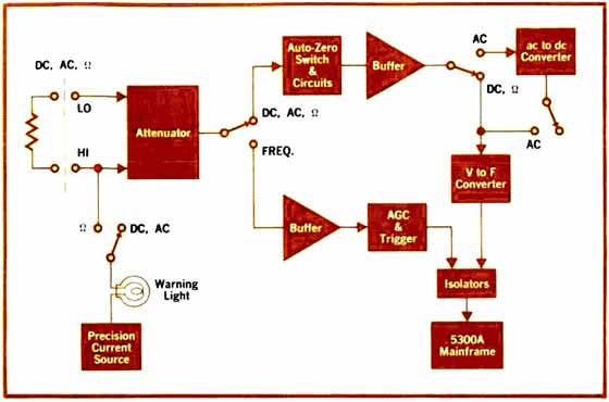
Fig. 3
5306/4 is floating and isolated from the grounded mainframe. For frequency measurements, the input signal is shaped by the 5306A and measured by the mainframe with six-digit accuracy and resolution.
Operation of the converter for a positive input voltage Vin is as follows. Vin goes to the integrator, and the integrator output is compared with a threshold voltage Vth. If the integrator output is more negative than Vth, then when the next clock pulse occurs (there's a clock pulse every five microseconds) the Q output of the flip-flop goes to its high state, routing the reference current IR, which previously flowed through CR2, now through CR1 into the summing node of the integrator.

Fig. 4
Voltage-to-frequency converter generates a frequency proportional to a positive or negative dc input voltage. (Omitted for clarity are comparator, flip-flop, and switch for negative inputs.) The auto-zero system derives a zero-correction voltage while the previous measurement is being displayed, then applies this voltage to the integrator input during the next measurement phase.
When the Q output of the flip-flop is in its high state, clock pulses are gated to the output. Thus the output signal consists of bursts of clock pulses at the frequency fin, which is the counter time-base frequency of 10 MHz divided by 50, or 200 KHz. The ratio of the average converter output frequency, fout, to the frequency fin is the proportion of time that the Q output is in its high state. This duty cycle, "8", is proportional to Vin, as the following equations show.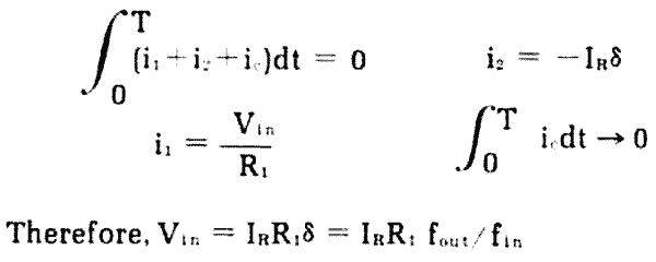
The reference for the measurement is the reference current IR. This current is derived in a straight forward resistor-amplifier circuit from a stable voltage generated by a pair of feedback-stabilized zener diodes. It is stable within about 10 ppm per degree C. Thus its stability is consistent with the overall reference accuracy specification of +/- 0.03%.
The V-F converter has five-digit resolution and range. However, zero drift from various sources would normally limit it to four-digit use. The autozero system reduces this drift to a level consistent with five-digit accuracy.
Auto-Zero System
The 5306A auto-zero system operates in two phases. During the display phase an electronic switch, represented by S1 and S2 in Fig. 4, disconnects the input voltage from the input amplifier and shorts the input amplifier to ground.
Any zero offset in the system causes a non-zero slope on the output of the integrator. The auto-zero circuit detects this slope and generates a correction voltage that is applied to the integrator to drive the integrator slope to zero. The closed loop residual error is less than 20 microvolts.
During the measurement phase the electronic switch disconnects the short on the input amplifier and reconnects the input voltage. A sample-and-hold circuit on the output of the auto-zero circuit holds the correction voltage derived during the display phase to compensate the measurement system for any zero error (Fig. 5).
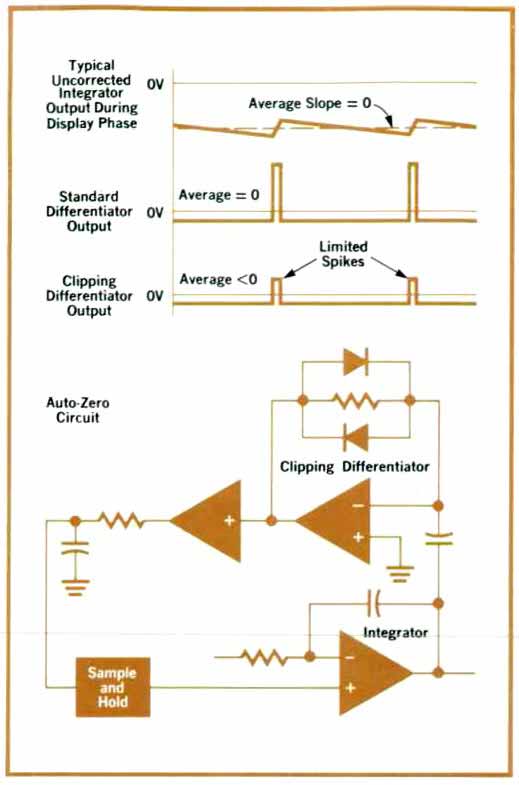
Fig. 5
Integrator output is ditterentiated to detect non-zero slope and derive the zero-correction voltage. Because the average output of a standard differentiator would be zero, a clipping differentiator is used.
The critical part of the auto-zero circuit is the detection of any residual slope on the output of the integrator. A simple differentiator could accomplish this except that the average slope on the output of the integrator is zero. The reason it is zero is that once the output of the integrator has reached the designated voltage reference, the reference current is switched on, rapidly driving the voltage back in the opposite direction. As a result, the average output of a standard differentiator would also be zero. This situation is illustrated in Fig. 5.
To operate effectively, the auto-zero circuit needs to reject the high spikes caused by the switching on of the reference current. The standard differentiator was modified into a clipping differentiator (Fig. 5), which limits the differentiation excursion possible.
The resulting output contains a dc component proportional to the residual zero error. This output is filtered and applied to the integrator through the sample-and-hold circuit to zero the system.
To thank the Author because you find the post helpful or well done.
Part 2: Measurements with the 5306A
Floating Measurements and Isolated Output
Another problem in adapting a multimeter to the 5300A mainframe was how to provide floating measurements. The 5300A mainframe is firmly grounded, and even if future versions could be made floating, potential users of the 5306A who already have a mainframe would have to undertake some kind of retrofit to achieve a floating system.
The alternative chosen was to float just the 5306A portion of the instrument. It meant that a separate power supply had to be built into the 5306A module. Furthermore, to obtain the output data, couplers had to be included in the 5306A to isolate the output channel. The secondary benefit of having isolated ground-referenced BCD output as standard rather than as an expensive option helped justify the extra cost of the couplers.
Ac Voltage Measurements
In the ac volts mode, the input signal is routed through the same input attenuator and buffer amplifier as in the dc volts mode. The signal is then half-wave rectified, and the resulting dc voltage applied to the V-to-F converter. This very common technique produces an average responding volt meter, calibrated to read rms volts.
The ac-to-dc converter is simply a precision halfwave rectifier followed by a gain-filter stage. The gain is needed so a 10 V rms input will yield 10 V dc output. The filter reduces the amount of ripple voltage applied to the master integrator.
Resistance Measurements
To make resistance measurements the precision current source used to measure negative voltages in the V-to-F converter is diverted to the input terminals. It passes through the unknown resistor producing a positive voltage proportional to the resistance. This is then measured by the other precision current source working with the V-to-F converter. This technique saves the cost of a separate current source for resistance measurements.
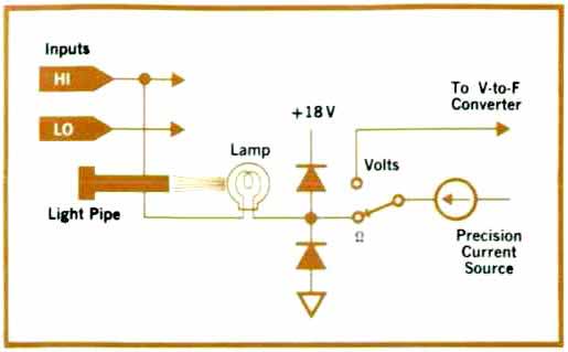
Fig. 6
Lamp acts as a variable resistance to protect the precision current source from damage and warn the user in case a high voltage is applied to the input during a resistance measurement.
For protection against external voltages the 5306A uses an interesting scheme. The precision current flows through an incandescent lamp before arriving at the input terminals (see Fig. 6). When a resistor is present at the input the low value of reference current (1 mA or less) fails to light the lamp and thus the lamp resistance stays low and doesn't disturb the measurement. Should a large voltage appear by mistake across the input terminals, current rushes through the lamp, heating it and increasing its resistance until the current is effectively limited. If a high enough voltage is applied the lamp will act like a fuse and burn out. The protection scheme is effective for input voltages as high as 240 V. As a secondary benefit of the lamp system, the lamp's glow is visible through a red insert on the front panel, thus warning the user that a dangerous voltage is present.
Frequency Measurements
Although a few voltmeters now have frequency as a standard function, these voltmeters generally convert each incoming count into a unit charge and inject this charge into an integrating circuit. They then measure the resulting voltage using a voltmeter technique and display the answer with appropriate frequency units. The resulting frequency measure ment has no more accuracy than the accuracy of the voltmeter, which at best is usually 0.01%. A dedicated frequency meter, on the other hand, counts each pulse using as its standard a crystal oscillator, which is usually accurate to parts in 10G or 0.0001%. This is the case with the frequency-counting 10-MHz 5300A mainframe. Therefore, to count frequency, the 5306A completely bypasses the voltmeter portions of the circuit and goes directly to the counting circuits of the mainframe, thereby achieving an accuracy commensurate with a dedicated counting instrument (Fig. 7).
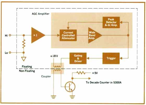
Fig. 7
Frequency input is common with volts/ohms input. Floating input allows frequency measurements in the presence of large common-mode voltages. Signal conditioning is done automatically rather than by frontpanel controls.
To maximize user convenience the frequency counter input is common with the volts/ohms input. This arrangement, for instance, allows the user to measure both the amplitude and the frequency of a signal with no change of test leads or switching of connectors, merely the push of a button. Also, since the frequency input and amplifier are fully floating, the 5306A provides measurement capability in the presence of large common-mode voltages. This useful feature is rarely found in generalpurpose counters.
Good frequency counters usually give the user input signal conditioning controls so that noise rejection may be optimized. To eliminate user adjust ments and yet provide reliable operation over a wide range of input signals, this optimization is done automatically in the 5306A. Noise rejection is generally provided by the deadband, or hysteresis, of the trigger circuit used to convert the input into a pulse train compatible with the digital counting logic. No noise signal can cause miscounting if its peak amplitude is less than the deadband of the trigger (the signal, of course, must be larger than the deadband). For optimum noise rejection we would like the deadband smaller than the signal but larger than the noise.
In general, there are two ways to adjust the noiseimmunity: vary the actual hysteresis of the trigger, or vary the amplitude of the signal fed to the trigger. The latter method is used in the 5306A and is ac complished with an automatic gain control (AGC) amplifier. The output of the AGC amplifier is aproximately constant for input voltages between lOOmV rms and 10V rms, and drives a trigger circuit whose deadband is about 30% of the peak-to-peak output signal swing. Over that range of input voltages, the noise rejection varies from about 60mV to about 6V, adequate for most applications.
Most ac-coupled frequency counters need offset controls or switches when they are used to count pulses or other low-duty-cycle signals. The 5306A can accept either positive pulses or 50% duty cycle signals like sine or square waves. Ordinarily, this would preclude the counting of negative pulses. However, the floating input will often allow the user to reverse the input connector, and thus reverse the apparent polarity.
The 5300A mainframe will accept count rates up to 10MHz. While it was easy to design an AGC amplifier and trigger for this range, it proved difficult to transfer the high-frequency signal from the floating input to the nonfloating counter. The solution to this problem is a coupling scheme which uses two closely spaced molded RF chokes as a pulse transformer. The speed was improved by using very low-inductance "windings" and driving the primary with high currents.
Acknowledgments
We would like to thank Ian Band, who provided technical advice, moral support, and overall guidance for the project. We would also like to thank Bruce Corya for the mechanical design, Steve Combs for the ac-to-dc converter design, and Larry Forman, Don Larke, Jim Feagin, and Rey Canio for successfully bringing the projects into production.
References
1. K. ]. Jochim and R. Schmidhauser, "Timer/Counter/DVM: A Synergistic Prodigy?", Hewlett-Packard Journal, April 1970.
2. R. M. Bracewell, "The Fourier Transform and Its Applications," McGraw-Hill, 1965.
PS from EE:
My thanks go to Arpad Roth, the schematic administrator of RMorg. He has prepared the pictures for me despite the fact that he has very much to do for administrating the many schematics which are uploaded.
To thank the Author because you find the post helpful or well done.
Which Multimeter?
The Model 5306A Multimeter/Counter module now makes available multimeter capability in two apparently similar though actually different snap-together systems. The other system is the 3470 Measurement System, described in (at that time) recent issues of the HP Journal.*
The modules for one system do not work with the display sections of the other. This is because the 5300-series modules convert all input quantities in to frequencies for conversion to a digital number by the 5300A Mainframe . The 3470 modules convert input quantities into a dc voltage for measurement by the 34740A (41/2 digit) or 34750A (51/2 digit) Display Sections.
With the wide range of capabilities that these two systems make available, chances are that most requirements can be filled exactly at reasonable cost. The decision of which multimeter to purchase will depend on what capabilities are presently owned, what capabilities are desired for present applications, and how the system may be expanded.
Present owners of 5300 Measuring Systems can add multimeter capability with the 5306A . Those not owning a 5300 or 3470 System currently should review the data sheets of both systems, considering their future needs as well as their present needs.
The 3470 Measurement System offers a selection of multimeter snap-on modules, a BCD-output in-between module, a battery pack, and two separate display units, one with 41/2 digits and one with 51/2. The 5300 Measuring System offers a 5-digit multimeter with frequency capability (Model 5306A), as well as a selection of frequency snap-ons, universal counter snap-ons, an analog-output in-between module, a battery pack , and a display module that includes B C D output.
Data sheets that give complete descriptions of both systems are available.
A . Gookin, "Compactness and Versatility in a New Plug-Together Digital Voltmeter. "Hewlett-Packard Journal, August 1972
.
R .Gardner, A Dumont, S .Venzke, "A Greater Range of Capabilities for the Compact , Plug-on Digital Multimeter, "Hewlett-Packard Journal March 1973.
To thank the Author because you find the post helpful or well done.
HP 6305A Specifications
The weight and the watts are given just for the module, not for the whole unit with the HP 5300B Measuring System (5300 B).
To thank the Author because you find the post helpful or well done.