ITM2M application
ITM2M application

Fellow Radiophiles,
My interest in tubes extends widely to any cold cathode device that glows. New unusual tube types surface occasionally from Russia. The latest such tube I have come across on ebay is the very pretty ITM2M Multicolor 4x4 pixel matrix with phosphor covered wells that glow when the internal gas has an ultra-violet discharge.
The operation is not unlike that of modern plasma TV sets. The plasma appears as the ultraviolet glow that illuminates the phosphor wells at the surface.
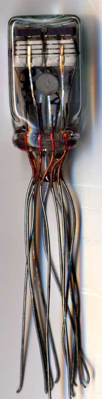
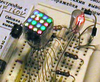 The tube has a square face that is one half inch wide. The depth of the glass envelope is over twice that. 12 wires extend from the bottom.
There are 4 sets of four colored pixels in Red, Yellow, Green and Blue.
Each pixel lights up when the row and column terminals are both grounded. The rows and columns may be grounded in any combination. Grounding all 8 control wires makes all pixels glow as shown in the photo.
The four remaining pins are assigned to ground, and three bias voltages. Main anode pin3 with 150VDC, secondary anode pin12 with 85VDC and the subcathode with -265VDC. See my English notes in the datasheets below.
Unlike with other Nixie tubes, current limiting resistors are not necessary. I confirmed this by curve tracing the 8 control inputs from 0V to +100V with the bias pins driven to their nominal voltages.. I used resistors as a convenient way to generate the various bias levels.
I drew a basic application circuit around the pinout diagram on the following data sheet. An 8 position dip switch drives the 8 matrix control wires, and the 3 bias voltages are generated directly from the 120V mains power.


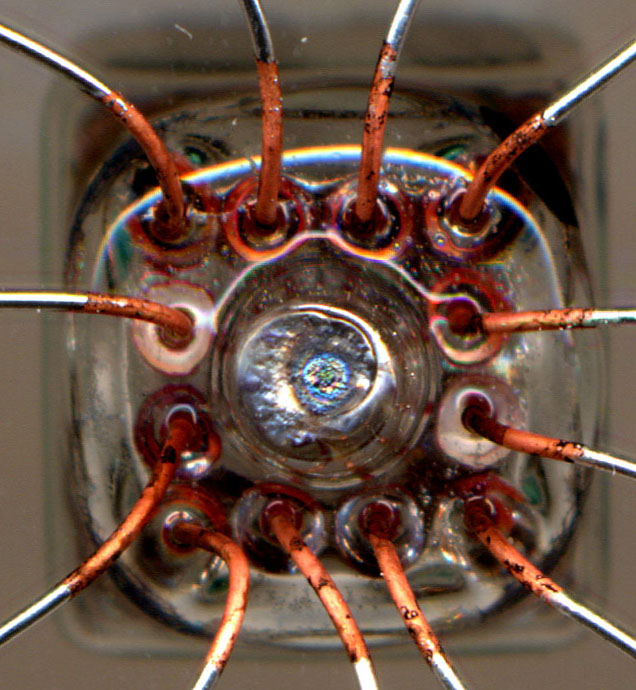
It appears that the operation within each pixel is something like a plasma gun, that is gated various metal layers that are isolated by ceramic insulators. When the pixels are lit, a faint blue glow is visible inside the tunnel at the center of each pixel.


I used dip switches for manual control of the pixels. NPN transistors with 330k pullup resistors to 160V in a common emitter configuration could be used instead. Suitable current limiting resistors (1Meg) could interface the base to CMOS control logic. The collector-emitter breakdown voltage Vceo need not be more than 100V.

The 4.7uF filter cap that turns the half wave rectified 120V at 60Hz is not stricktly necessary. If you remove it , the bulb still functions, but runs dimmer. You can double the brightness if you are not using the cap by replacing the single half wave rectifier with a full wave bridge.
The 2.2uF filter cap for the negative -265V supply is also not stricktly necessary, it simply turns the 0 to -320 swing from the 4.7uF cap in the negative supply into -320V DC. Same effect on brigthness.
One advantage of the single cap supply that uses just one 4.7uf cap to generate 0 to -320V AC, is that it takes a less positive voltage at any of the 8 matrix inputs to turn off the pixels because even if one pixel fails to turn off due to insuficiently positive voltage, the periodic extinguishing of all pixels takes care of any stuck-on pixels.
Regards,
-Joe
To thank the Author because you find the post helpful or well done.
CD4060B drives ITM2M
The CD4060B CMOS 14 Stage Ripple Counter is the ideal single chip driver to show all the possible patterns on the ITM2M Russian plasma display, because it can swing up 20Vp-p to drive the 8 control cathodes.
The original RCA version of the CD4000B family was rated for operation up to 20V. Some of the recent versions operate up to 15V. I use 15V, which is enough to cross the 7V turn-on threshold I measured at the control cathodes.
The CD4060B can even be wired to self-clock with RC or crystal timing, and it is guaranteed by design to be 100% software-free!
The 8 row/column pixel control cathodes are active low.
A close inspection of the electrode arrangement has revealed the following sequence, starting from the display surface:
ITM2M electrode layer order
1-Anode High at top near phospors
2-Anode Low
3-Ground
4-A layer with 4 rows of cathodes
5-B layer with 4 columns of cathodes
6-Cathode at bottom
There are 4 control rows of cathodes and 4 control columns of cathodes. Up to 256 patterns can be supplied to these 8 control electrodes, however, all pixels will be off if all the columns or all the rows are high. This leaves out 16 codes if all the rows are high and an additional 15 codes if all the columns are high.
If a straight binary count pattern were to be applied to the 8 control wires, there would be blank periods while either the rows or columns count through 16 stages when either the 4 corresponding colunms or rows are all high.
Swapping the 8 control pins in different orders simply reorders the sequence of the 225 possible patterns of pixels.
An alternative chip to demonstrate the pixel patterns with a random count would be the CD40106B hex Schmitt trigger configure as one oscillator per inverter with one resistor in feedback and a grounded timing cap at the input. All the time constants could be picked to be the same because, soon, the various oscillators will drift out of sink for interesting patterns. This requires two chips, 8 timing resistors and caps.
Yet another interesting pattern generator would be a Gray counter fashioned from CD4000B logic. The Gray counter would change states only one bit at a time.
If a micro-controler is your toy of choice, then a CD4504B could do the level shifting from a TTL swing to 15V to drive the row/column control cathodes.
Operation of CD4060B driving the ITM2M
As I hinted in the previous post, the key to control the row/column cathodes is to turn off the ITM2M so it can be easily triggered into a new state. This is necessary because once a cathode is triggered on, it may take bringing the cathode near the Low Anode voltage of (~70VDC) to turn it off.
This trick was once very common to control cold cathode bulbs in the 1950's and 1960's.
If the tube starts in the all-off state, it only takes bringing the row/column control cathodes below 7V for turn-on. +15V at the cathodes keeps them reliably off.
One very easy way to keep the ITM2M ready to accept any new row/column patterns is to drive one of it's bias electrodes with an AC or pulsed voltage. The operation is similar in principle to that of a TRIAC in a light dimmer that can be triggered once per AC cycle, but can only turns off when the AC voltage crosses zero.
I chose to apply pulsed -320V to the Cathode at pin9 to reset the ITM2M once per line cycle. This choice saves one rectifier diode and eliminates the need for a filter capacitor that is rated to take 320VDC. Now only two 4.7uF 160V capacitors are needed in the power supply.
The CD4060B takes 15V regulated by a 15V zener diode. R1=22K dissipates 0.9W, so a 2W size is recommended, or you could make R1 from 4 100k 1/2W resistors in parallel.
Keep in mind that this circuit is not isolated from the AC mains. If your circuit involves a micro-controller, be sure to use an isolation transformer to program the controller in real time, or simply program the micro controller separatelly.


The reset button on the left forces the CD4060B outputs low and provides a handy all-pixel-on test.
I soldered a 5W resistor to the turn screw of the multi-turn 500k trimmer for convenient clock speed adjustment. When the pot is turn all the way to zero, the count may become erratic, but too fast to see, anyway. If fast rates are preferred, a value for CR that is smaller than 0.1uF should be used.
The green heat shrink tubing over the 160V 4.7uF cap on the lower right prevents my wayward fingers from getting tingled with -320V pulses. Note that this cap only stores 160VDC. It delivers -320V pulses by riding on 120VAC.
I always add a fuse to all my projects and to most radios I restore. The 125mA fast blow rating will survive the turn-on current to charge the caps. A more optimal fuse rating could be chosen at lower currents with slow blow operation. The total current draw is just under 20mA with all pixels on.
Be sure to swap around the various row/column wires for different pattern sequences.
Regards,
-Joe
To thank the Author because you find the post helpful or well done.