korting: 22322; Noblesse
korting: 22322; Noblesse

Today I was trying to repair my Noblesse 22322 (Körting)
It is the present tread:http://www.radiomuseum.org/dsp_modell.cfm?model_id=54720
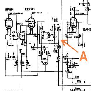
I was following its schematic (2) (also in Rmorg) when I found this in it:
A short-circuit arrow A ( not in my set, but in its schematic :-)
(2nd Coil of BV4059 I.F. and C401 condenser).
In my set I've a missing component nearly. Perhaps, instead of a line, there might be a component, or an open circuit. Who Knows?
Yes. Who knows?
Do You? Then , I thank You in advance for any information.
Will You do ? Do You? As Mr. Ernest already said before about this radio set: "Noblesse oblige". :-)
Cordially
Mário
To thank the Author because you find the post helpful or well done.

this connection is wrong.
No additional Component is necessary for function.
What whe can learn? Orign. Factory Information ( here Körting) can also include, errors!
Best regards from Hans
To thank the Author because you find the post helpful or well done.
Which option?
Hello Herr Hans
Thank you for your prompt and expert reply.
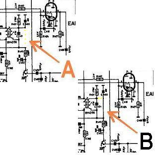
There are two options: A and B.
Which one is the right one?
The schematic is still in Rmorg. I think should be better to correct it, or to add a note in it. Don't You?
Meanwhile I'll try to understand which component is missing in my set. I'll be back because this set is quite singular. Ex: It has one EAM86 (this tube works, glows fine, but my Tube Tester says it is exhausted). May be the amp. section?
Best Regards
Mário
To thank the Author because you find the post helpful or well done.
Version "A" is the right one.
Because the Tunig Indicator, i must study the Circuit and give you Informations later here.
First, the Triode Part is only for Audio Amplifiering.
It is possible, that the low Anode current in this cases gives a good Performance, but Test on Tube-tester with higher current ( as indicator ) say "bad"
see here my explanations to this situation.
http://www.radiomuseum.org/dsp_forum_post.cfm?thread_id=50704
regards, Hans
To thank the Author because you find the post helpful or well done.

Your explanation of EM8X, EAM8X tubes functions as well as Körting "Nobeless" delayed AGC was very interesting and clear. Thank you.
BR
Ake
**
To thank the Author because you find the post helpful or well done.
thats fine. Koerting have and makes always interesting Circuits.
In this case the "generator" for an negativ Voltage, complete free of potential ;-)
regards, Hans M. Knoll
To thank the Author because you find the post helpful or well done.
Hallo Mr. Hans
Thank you again for your clear and complete explanation.
I already bought a new EAM86, to compare.
Well. This new one has a best performance. The tube tester says it is OK.( the last one was exhausted).
But when I perform the second test (the other stage) the galvanometer pointer didn't move. But it glows as the other tube did.
Do You agree with this conclusion? :
1-In the 1st part of test, the amp. Stage was tested. In the second part of the test, was tested the Tuner indicator.
2- The fist tube was exhausted. The new one is good.
3- My tube tester doesn't test the performance of the tuner indicator stage.I need to look to the tube to see if it glows or not.
---o---
About the missing component.
I present one picture of two terminals (leads) (A) where I presumed a component is absent.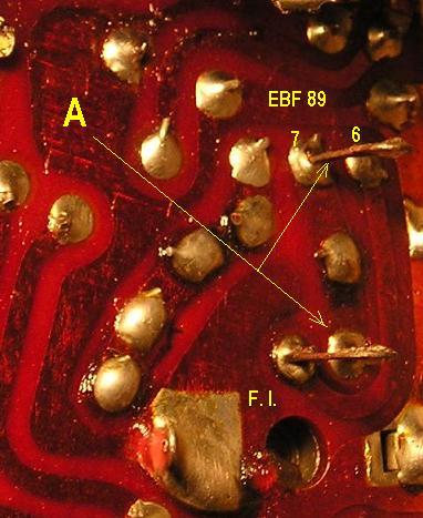
One component between these two terminals should link pin 6 and pin 7 of EBF 89.
Nevertheless I can't perceive in schematic any component.
Are those terminals not to use, but only "testing points"?
Thank you for your time and patience
Best Regards
Mário
To thank the Author because you find the post helpful or well done.
Tube testing?
your questions:
Do You agree with this conclusion? :
1-In the 1st part of test, the amp. Stage was tested. In the second part of the test, was tested the Tuner indicator.
2- The fist tube was exhausted. The new one is good.
3- My tube tester doesn't test the performance of the tuner indicator stage.I need to look to the tube to see if it glows or not.
My answer: i agree at all points.
I not now any tubetesters, but in now many. ;-)
All testers, make a measurment at Amplifier section e.g. bad , good or how much mA.
also all makes an visualtest : shadow with, shadow small.
Missing part:
an designer has tree posibilitys to generate Audio and AGC Signals from the IF Signal.
In simple units they are using only one diode like (EABC80).
or two diodes in different ways.
in my hand-drawing i show you these versions. Blacklines your set, redlines PC Board with alternation posibility. I think is to hard ( for you) to explain why?
New: this example of AGC generating, is only to show what is the posibility of the circuit or variation from designers, to find a solution to solve requirements. Not to change this Set Noblesse!
30.04.05
I hope you agree.
best regards, Hans
To thank the Author because you find the post helpful or well done.
Its new for me
Hello Mr. Hans
Of course You know very much about tube testers. Nobody doubts it. For me is different. Almost of this matters are novelty to me . J
I didn't know that ,with my Tube tester, tune indicators performance couldn't be evaluated in mA, as can be in the other stages. I began this hobby two years ago with very few knowledge about. I'm not even a junior yet. :-)
About AGC:
May I understand that I need to put one condenser between those leads?
(As I said before I can't see any component in its schematic between pin 6 and pin 7).
If yes, do you suggest a value?
Best regards
Mário
To thank the Author because you find the post helpful or well done.
please change nothing. This versions is only for Koerting designers ( on Labratory) a option for an alternation!
The Set must working well in the blacklíne version. 10 pF between pin 7 and 8.
Hans
To thank the Author because you find the post helpful or well done.