Magnetic Circuits: A few interesting cases
Magnetic Circuits: A few interesting cases

Fellow radiophiles:
I have sometimes wandered into the mysteries and wonders of magnetic circuits. A magnetic circuit is formed when a magnet or energized coil have their flux conducted via a particular path. For example, transformers, chokes, loudspeakers and motors all have carefully designed magnetic circuits, where the flux is conducted through high permeability steel (relative permeability, μr>>1000) and through carefully designed narrow gaps. In some cases, a permanent magnet is involved in other cases only current-induced fields are involved.
One can make an analogy between a magnetic circuit and an electric circuit. Air and vacuum have low permeability with μr=1, which is analogous to a low conductance (high resistivity) medium in an electric circuit. Ferrous metals have generally very high μr>>1000 and are analogous to a very high conductance (low resistivity) medium for an electric circuit. In the magnetic circuits discussed below, only air gaps and very high μr>>1000 materials are considered. Given the great difference in permeability in some cases the magnetic field flowing through the air is small enough to be neglected and the ferrous metal path can be thought of as a magnetic short circuit where nearly all the field is conducted.
It took me most of my 40 year engineering career to understand some of the more interesting magnetic circuits, mostly because I did not need to understand them professionally and also had not studied them at length in school. So here go a few interesting cases that I collected along the years.
D'Arsonval-Weston movements
 The D'Arsonval-Weston movement is the most common kind of meter movement. As the illustration from Wikipedia shows on the left, a pivoted coil holds a pointer and rotates up to 90o with the force generated by the magnetic field of the current passes through it. The magnetic circuit is incomplete in the illustration. The pole pieces labeled N and S are just the ends of a horseshoe magnet. So the complete magnetic circuit has the horse shoe magnet, the cylindrical piece of ferrous metal inside the coil and the air gap separating the metal cylinder from the pole pieces. The separation in the air-gap is kept as constant as possible along the gap to maintain linearity of deflection. A narrower gap section would deflect more, thus degrading the linearity of the instrument.
The linearity is owed to the high ratio between the mu-r of 1 for the air gap and copper coils and a hugely higher (μr>1000) for the magnetic circuit metal path. The very high mu-r on the metal pole pieces distributes the magnetic flux very evenly along the gap because it looks like a magnetic short circuit compared to the gap.
The pole pieces are analogous to the metal  end caps of a rectangular chip resistor as illustrated on the left. The black material in this illustration is the bulk resistance material and is analogous to the air gap in the magnetic circuit. The conductivity of the resistor metal caps is very high compared to the resistive material, just like the permeability of the pole pieces is very high (μr>>1000) compared to the permeability of the air gap (μr=1).
The current flows are very evenly distributed along the resistor end-caps, just like the magnetic flux flows are very evenly distributed along the pole pieces at the air gap in the magnetic circuit. The magnetic circuit of the D'Arsonval-Weston movement consists of two air gaps in series with the permanent magnet and in series with the fixed ferrous metal cylinder inside the deflection coil.
270o deflection meters
 Related to D'Arsonval-Weston movements, I own three analog meters with 270o deflection instead of the customary ~90o deflection of standard D'Arsonval-Weston. It was only today, that I finally peered into one of these meters while observing the 270o deflection, that the operation became clear. Here the magnetic pole pieces are Q shaped, where the little dash in the Q represents where the two pole pieces meet. The two pole pieces may be concentric or simply stacked one above the other, with the needle pivoted at the center of the Qs and the deflection coil gliding along the inner, or perhaps top, Q pole piece. The coil force is exerted at the gap between the two Q pole pieces. One pole piece has one magnetic pole and the other has the other magnetic pole. The magnetic circuit is completed between the two Q's with a bridge of ferrous metal behind the movement. The coil is plainly visible in the photo just to the right of the pivot. It glides along one Q-shaped pole piece. Pretty elegant solution and a bit surprising that these came along relatively late in the analog meter era. A bit like a linear magnetic motor or speaker voice coil gliding in a curved path.
By the way, the magnetic flux distribution along the gap of a speaker is also very constant for the same reasons that apply in these meters, to achieve a very constant flux density along the gap for a very linear deflection.
Current probes
 For a long time I wondered how the magnetic flux of a current clampmeter worked. Here again, it is the huge mu-r of the metal pole pieces that makes the air around them look like a magnetic insulator. So approximately all (>99.9%) of the magnetic field produced by the wire going through the clamp goes through the pole pieces that clamp around the wire to form a toroidal core. Wire position becomes unimportant. The critical thing for accuracy is a very tight clean gap in the clamp to keep total magnetic loop reluctance predictable as a seamless toroid.
Early DC clamp meters use metal that is easily saturated with strong chopping currents and the DC field of the current being measured gently moves the saturation points, which are then monitored in a tight high gain servo loop. The drive current required to counter-act the current under measurement becomes a representation of the AC and DC currents under measurement. This is called a flux gate arrangement.
For more detail on a flux gate clamp operation, look up the manual for the HP428b clamp-meter. My wonderful HP428B, AC/DC clamp-meter, which is nearly as old as I am (>60yo) sports the amazing current measurement range from 1mA to with 10uA resolution, while also reading up to 10A in the top range. Of course, you can't blow up this meter if you try to measure 10A in the 1mA range! You just need to demagnetize the pole pieces in the rear of the instrument. I wonder if some additional built-in coil could not have done the demagnetization more conveniently. This meter has a BNC output with DC-400Hz BW, that can be viewed on the scope or measured by DC or AC voltmeters. This is one of the essential instruments to work on old radios, that usually have plenty of wires, around which the clamp can fit. One of the more basic uses is to monitor AC current into the radio, where you can monitor peak rectified currents on the oscilloscope.
There are also semiconductor Hall-effect sensors that can be used instead of the flux gates. These have much higher signal bandwidth, while still measuring DC currents.
Shaded pole motors
 I came to understand the operation of shaded pole motor operation over a long time. I few years ago, I took a closer look at the fields using little wire loops in the gap of a small shaded pole motor. This is the rectangular type shown in the illustration with a single drive coil and a pair of small shorted stator pole pieces opposing each other across the rotor as shown in the detail illustration with the rotor removed. The copper of the shorted loops is visible at the top of the steel frame. The field through the shorted loops takes longer to change, thus causing a phase shift. The loops shade the phase-shifted poles. This phase shifted magnetic field creates a rotating field when combined with the portion of the field that is not phase shifted and went directly to the rotor without passing through the shaded poles with the shorted loops.
For one, the shading is more than pure phase shift; it goes all the way to hard saturation, which further delays the field, this explains why they are so small, so they can be easily saturated. Another interesting bit is that the vast majority of the magnetic field through the rectangular frame goes straight through the ferrous steel rotor without any phase shift and without trying  to rotate the rotor. This arrangement makes it possible to tie the coil directly to 120VAC and most of the magnetic circuit is involved in forming an inductive ballast. The comparatively tiny field that is delayed by the shaded poles is half of the field involved in motive force and the other half is a small portion of the non phase shifted field.
The further interesting bit is that, in practice, the shaded field and a small portion of the direct field form two small rotating fields at the gaps under each of the opposing shaded poles. It is as if the rotor were being pulled along by two small magnetic rollers at the shade pole gaps. Weird, two lateral spinning magnetic fields on opposite sides of the rotor do all the motive work! The field straight through the rotor is involved only in inductive ballasting. This also explains why the rotor must be made of high mu-r magnetic material to complete the magnetic ballast circuit path. The rotor is also electrically conductive for the necessary induced eddy currents involved in the inductive propulsion.
Reluctance motors
 One nifty further refinement I noticed in one of the "induction" motors I bought to study, that turned out to be a reluctance motor, is that the rotor steel can be chosen to be easily magnetized and demagnetized with a permanent field. This means that the rotor steel in the reluctance motor will have a harder hysteresis curve than the rotor in the induction motor above.
This makes the motor operate in two distinct modes: At full speed, the rotor retains a modest permanent fixed magnet field and rotates synchronously with the power line. At lower speeds, the "permanent" magnetic field is rotated synchronously with the power line against the slower rotor to contribute more motive force than what simple induction would produce. There is a clear speed threshold effect that can be seen with my General Radio Strobotac tachometer on a motor of this type. The motor model is a "reluct syn motor", made by Eastern Air Devices of Dover NH. If you grab onto the shaft, you can see the speed go in and out of synchronous lock under the tachometer light, but once out of lock, it has much higher torque than a comparable induction motor, like a simple fan motor. It is pretty easy to break the sync lock under load, so the fully loaded operation is likely designed for rotating speeds slower than synchronous lock. The zero speed torque is also much higher. This motor has more conventional stator orthogonal windings with a capacitor providing phase shift for one of the winding sets. Wikipedia has more details on this motor.
Single coil stepper motors


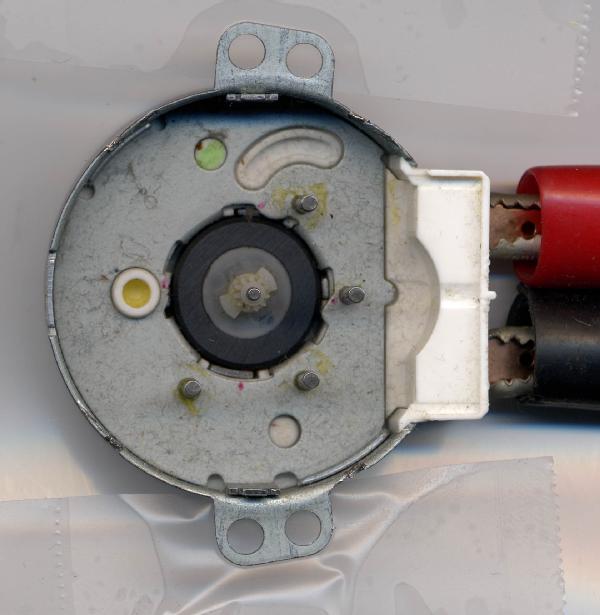
The wildest motor of all, is what is used universally to rotate microwave oven platters and in mechanical wall timers. It only has a single coil in the stator, that is wound around the rotor with the axis of the coil parallel to the rotor shaft. This is at 90o to most other motor configurations. The coil is under the top steel pole piece shown in the photos. The important path of the magnetic circuit flows through: the top pole piece, the side of motor housing, the bottom pole piece and its fingers through the magnet and back through the top pole piece fingers and to the top pole piece.
The rotor is shown removed in the middle photo. It is relatively wide, about an inch in diameter and has a ring magnet with 4 pole pairs made out of plastic synthetic magnetic core material. Something like the bulk version of magnetic recording tape. At rest, if you hand spin the motor there is a very clear cogging force.
The stator has top and bottom pole pieces above and under the single coil, with 4 fingers each that mesh from the top and from the bottom around the periphery of the rotor.
The 4 top stator fingers are identical and evenly spaced around the rotor. The bottom stator has 2 fingers opposite each other, that are the same width as the 4 top fingers. The other 2 bottom fingers are less than half the width. These narrow fingers still oppose each other, but are rotated together to one side, so that they are not evenly spaced with the wide fingers.
The crazy bit is that you can actually step these motors discretely with a center-off SPTT (Single Pole Triple Throw) switch, simply by sequencing four states of positive and negative DC current into the coil, with zero current states between the positive and negative current states. The magic is apparent when the power is removed. The rotor actually rotates further maybe a few degrees between the last powered state and zero power. If you apply the reverse polarity, to the single coil, it snaps to the next location and when you remove the power it moves another few degrees in the same direction.
The magic is that with power applied and power removed, the physical magnetic circuit path is slightly different. The motor relies on the two extra narrow pole pieces, with one of these visible at the bottom of the third photo above, that are more easily saturated than the others, thus "disappearing" because of saturation, from the magnetic circuit under power. So the stator is reconfigured with a slight rotation in the off state vs the powered state. Crazy elegant!
Without power applied, the rotor poles are somewhat rotated with respect to the stator, because the narrow fingers are shifted away from the 90o positions with respect to the other 2 wide bottom fingers. When power is applied these narrow poles are virtually attenuated or deleted and the poles in the magnet ring can now line up more evenly with the poles of the stator, that now look more symmetric.
The following sequence of 7 photos was taken with the sequence +28V, 0V, -28V, 0V, +28V, 0V, -28V applied to the coil. You could download each of the photos with a right-click and then view them in your computer in slide show mode to see the subtle rotation of just a few degrees when entering the 0V state. The title of the downloaded photos indicates the applied voltage as p28V, 0V and m28V.

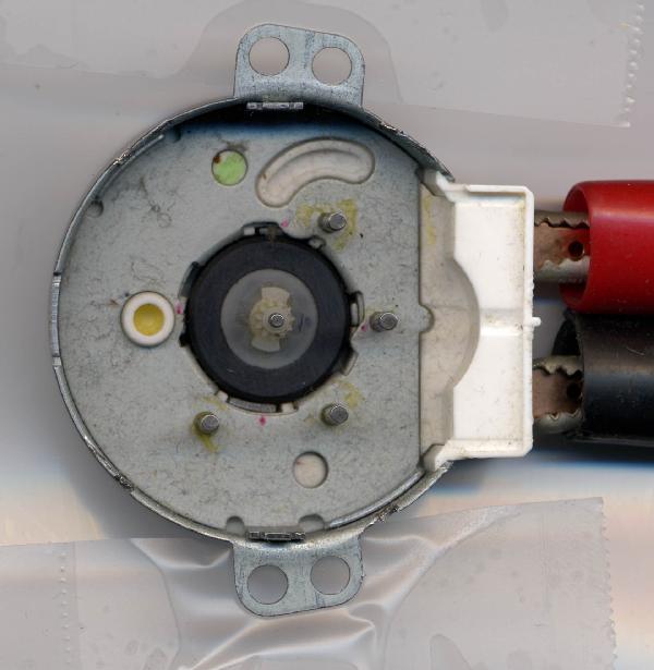


I built one of these motors into a demo circuit where I drive it along with the 4 sequential states about 1sec each, alternating positive and negative voltage with zero power between these two. Or manually with an SPTT switch. I attached a pin with a red head to the shaft to serve as a pointer and clearly show the few degrees of "rewiring" of the magnetic circuit when power is removed.
One of the useful properties of this arrangement is that it makes the rotation unidirectional. Synchronous motors can, otherwise spin in either direction, unless something is done to insure rotation in a single direction.
Being synchronous, with permanent magnets, these motors are powerful for their size, so they fit neatly under a microwave platter and have no trouble rotating a bowl full of food.
I thank my work colleague Suparna Das for giving me this motor to play with. I always turn to him when I think about magnetic circuits.
Regards,
-Joe
To thank the Author because you find the post helpful or well done.