Marconiphone 221 RESTAURATION NOTES
Marconiphone 221 RESTAURATION NOTES

Marconiphone 221
I acquired the set on 11.12.2016 without valves and I couldn't find the circuit diagram and/or any information about the valves that may equip the set.
RESTAURATION NOTES
Finally I had to draw the circuit diagram following the wiring on the chassis. (Takes a lot of time & patience, but if the result makes sense, its fun.):
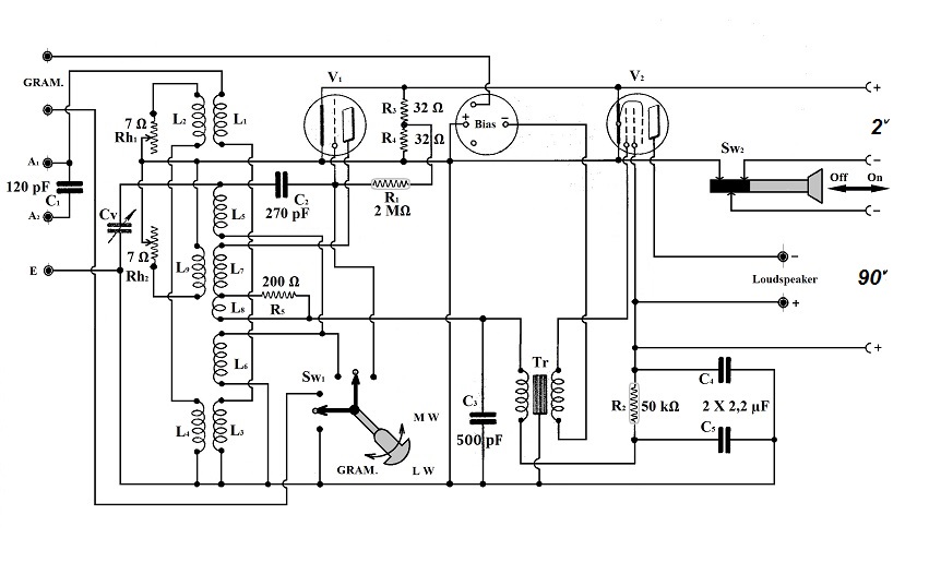
First stage: regenerative detector on upper bend of a triode. Very seldom/strange regeneration/level control: Separate windings in parallel with rheostats meant to shortcut them. (More or less.)
Second stage: transformer coupled AF amplifier employing a pentode.
Design faults found & repaired
The pads underneath the cabinet were in a pitifull state so I replaced them:

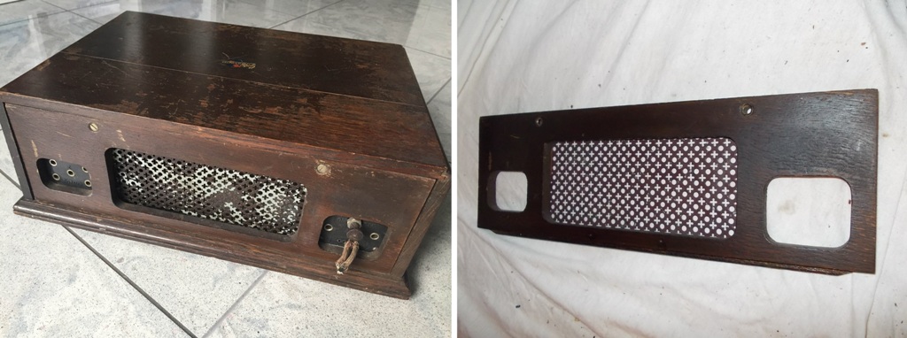
The paint on the metallic grid of the rear panel was half gone. I put a new coat:
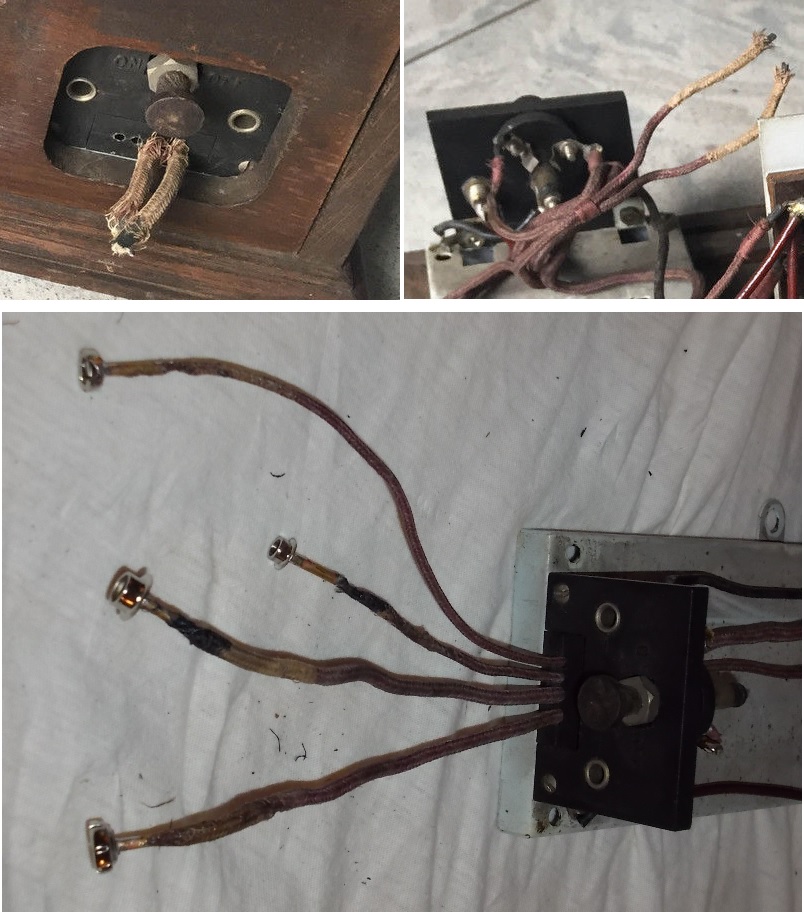
The power supply connections were cut and in disorder. I sorted them out and soldered appropriate connectors to accommodate modern batteries:
Circuit faults found & repaired
Terminals from grid resistor R1 (2 MΩ) of the first valve: broken
In the pictures the vendor posted, one can already see that a terminal was broken. During the transport, the second one broke too and I found the resistor lying inside the cabinet after I unpacked and opened the set. The copper wire terminals become brittle with age.

First, I tried to solder two pieces of copper wire, directly on what was left of the terminals, but the butts of wire protruding from the glass envelope were so small that I couldn’t get enough mechanical robustness. The minute solder points could not safely sustain the relatively heavy glass tube containing the resistor.
The value of the resistor hasn’t change too much with age: I measured 2.86 MΩ and I decided it could be kept in circuit. After all, these resistors enclosed in vacuumed glass tubes were supposed to keep their values “for ever”. By the way, the other resistor of this type, R2 marked 50.000 Ω was measured with 53 kΩ. (Not bad at all!)

In order to obtain “Heavy Duty” terminals for R1 I was forced to compromise a bit the appearance. (Possibly some “Hard-Core” collectors would condemn me.)
I took two caps from a “Sofite” lamp, I half-filled them with hot solder, I pressed the ends of the glass tube inside and I hold them tight until cold.

The resulting terminals are definitely robust, could be cut, bent and even soldered.
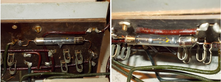
Finally I put R1 back where it belongs.
Grid-bias divider of the first valve R3 + R4 (2 X 30 Ω): interrupted
R3 and R4 consist of two sections of resistor wire wound on a small Pertinax plate affixed flat on the chassis with two screws and nuts, practically hidden underneath the bias socket. It’s not easy to extract it from there. One needs patience, good tools and a sure hand.

Once the small plate extracted, I could find & solder the broken resistor wire on the grid-bias divider. It was only R3 which was broken towards the middle point.
R4 measures 31.3 Ω and R3 (repaired) 30.8 Ω.

After coating it generously with transparent nail polish (one can also use “Zaponlack”) and let it dry, I put the grid-bias divider back with the required care:

Dealing with this part of the set I was struck by two peculiarities:
1). The use of a permanent and fixed voltage divider for biasing the grid of the regenerative detector.
2). The use of a valve socket as a connector for the bias battery.
Blocking (double) capacitor C4 + C5: has lost its value
The tar layer which was supposed to insulate the inside from moisture was broken so I was not surprised when the measured capacity was almost nonexistent and the resistance in the kilo-ohm range. I took the metallic case out of the set and turned it on all sides – no markings - so finally no way to find out which values would the inside capacitors have had.
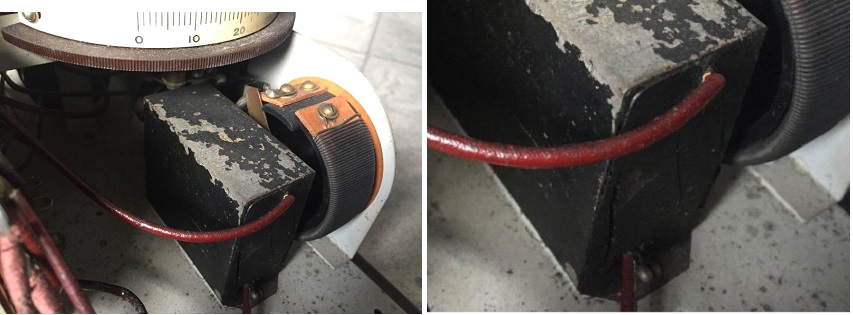
Melting the tar, (it’s genuine tar – smells like Hell when meted!) I extracted the contents from the metallic case and I soldered a flexible wire inside it:

I carefully separated the old terminal wires, put inside the two 2,2 µF /250 VDC (un-polarized) modern capacitors which, after soldering the wires, I stabilized with some tar.

After measuring 2,2 µF between case and ech of the terminals, I filled the rest with tar and I put the restored double block capacitor back where it belongs:

Interstage AF transformer Tr: primary & secondary interrupted
I took the transformer out and I dismantled it hoping to find broken wires or other faults that I could easily mend. It was not the case.
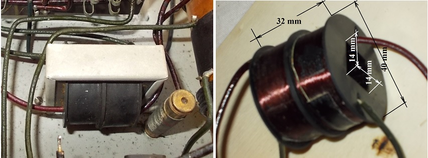
Than, realising I have to do it “the hard way” I started measuring the old windings form, and the iron core, in the meantime looking for some cheep Chinese transformers of proper size.
The idea of replacing burned or interrupted old interstage windings with new readymade (taken from cheep modern transformers) does not belong to me, I just took it from an article named “Transformateur B.F. d’un poste C119” printed in “Radiofil Magazine N° 65” November – December 2014. Of course I adapted it to my needs.
I had no means to find out which was the original ratio of the transformer but measuring the iron core and the former of the new windings became clear that I cannot squeeze more than 3 formers on the available space:
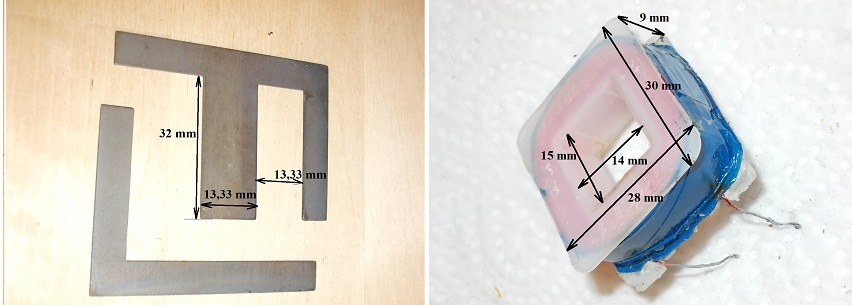
It will have to be a 1 to 2 interstage transformer one winding alone being the primary, and the other two connected in series, the secondary. Usually an interstage for a two-valves set has a ratio from 1: 3 to 1: 5, but me having no coil winding device, I honestly had no other choice.
Consequently I dismantled three small 220V to 9 V transformers; I took only the primary windings and put them to the old core:
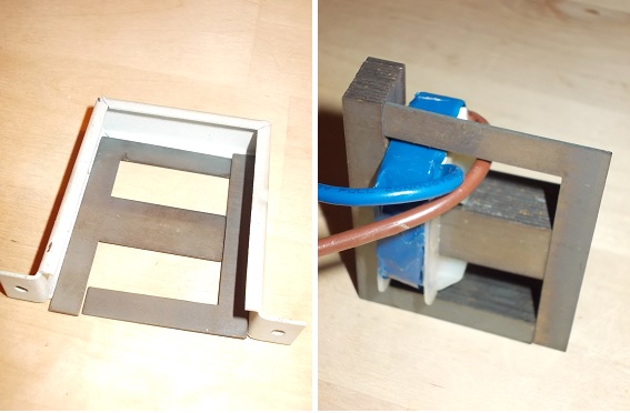
To get them all three tight on the core, I had to cut and (gingerly) polish the plastic protuberances on the sides of the formers.
Finally, with (black) cardboard and (black) robust paper I shaped a black envelope the approximate size of the old former to hide the new wires, the hideous plastic formers and the infinite blue of the new windings.
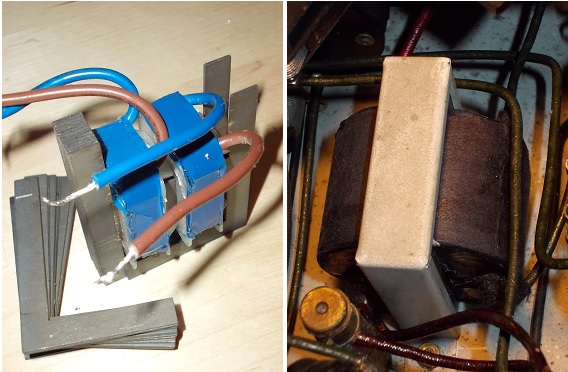
That goes without saying that I stripped the old terminals and used them for the new transformer which I put back where it came from.
WORKING TESTS
Preparing the Tests
The sockets for connecting antenna, earth and loudspeakers are 3/16 inches (4.7625 mm) in diameter and not 4 mm. I had to look for cheep banana plugs which could be bent to (approximately) match the sockets:

Then I connected the batteries: 2 X 1.2 VDC D size accumulators and 5 X 9 VDC batteries. I always start carefully, with a lower anode voltage.
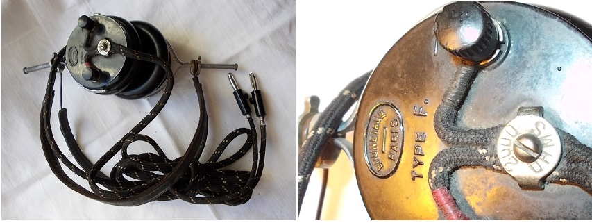
Since I plan to begin with the test of the first stage alone I chose some sensitive headphones, the “BRUNET & C-IE. PARIS TYPE F.”:
Not knowing what kind of valve originally equipped the first stage, and not wanting to risk any of the valves from my collection, I took the cheapest (extremely robust) Russian military valve 2Ж27Л and wired it as a triode using a Loktal socket and a B4 plug:
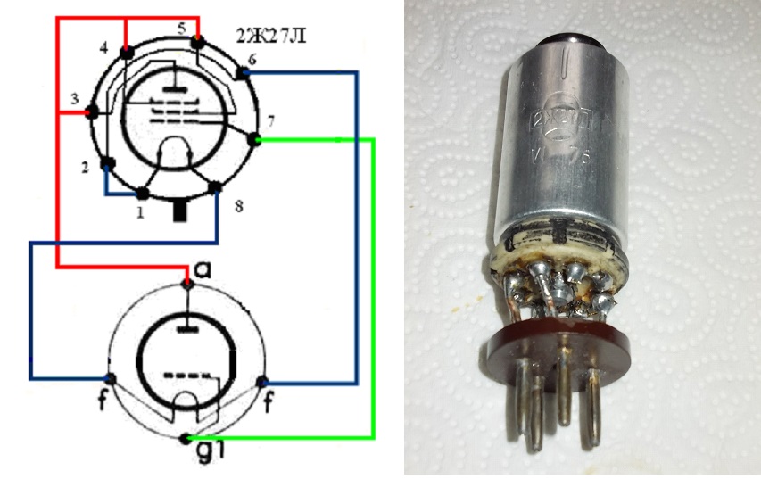
All three sockets on the set are B5, but only by the last one, the middle contact is connected (the power AF stage using probably a pentode).
First working test
I inserted the valve, I made a bypass connection (shown in red on the circuit diagram) with a flexible cord (having alligator clips at both ends) and (knocking wood) I powered the set. With the band selector in LW position I could hear some squeals and whistles by turning the variable capacitor.

Fighting with the regeneration control and adjusting carefully the variable capacitor, I got some three French-speaking broadcast stations and faintly BBC 4.
On MW I heard Brussels (621 kHz) heavily engulfed in noise and interfered. I cannot hope to hear anything else during the day on my location (Leverkusen) even with a more sensitive set.
I can safely conclude, the first stage works pretty well and my meddling with the set did nothing to hamper its functioning.(Yet.)
Second stage under test
Meanwhile, the interstage transformer was patched and put back in its place. The time to test the second stage has come. It should (theoretically) be equipped with a power pentode, but for the beginning I decided to use the same 2Ж27Л this time wired as a pentode using a Loktal socket and a B5 plug:
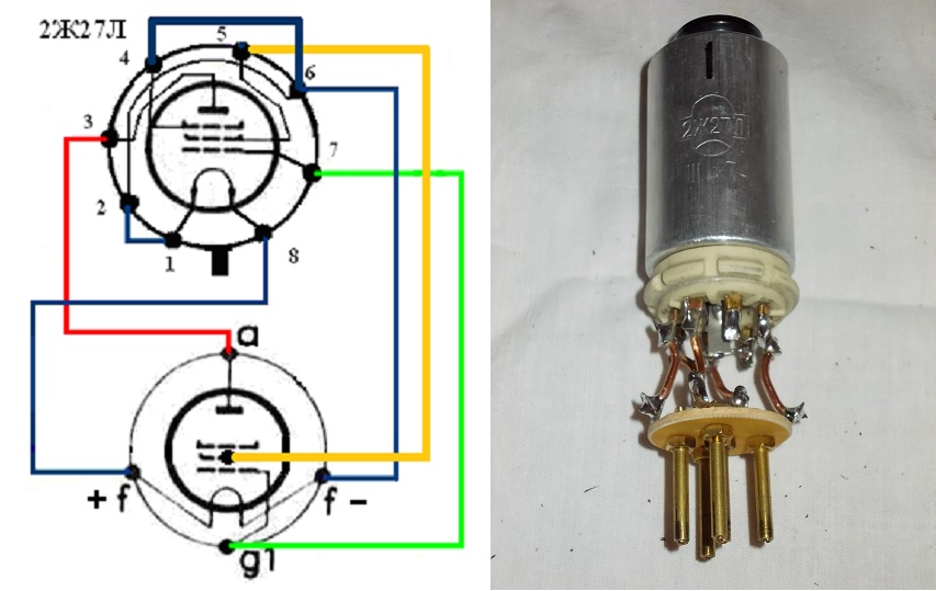
After plugging-in the second 2Ж27Л I started thinking which horn-loudspeaker could I risk for the test but I couldn’t decide.
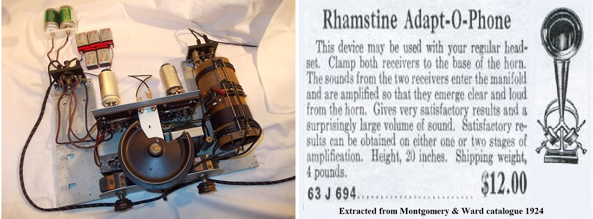
Then I recalled that some time ago I “home-brewed” an “Adapt-O-Phone”, very useful when the set I’m working at, starts shouting at me through the headphones: I can save my ears and continue working by putting the headphones on the adapter:
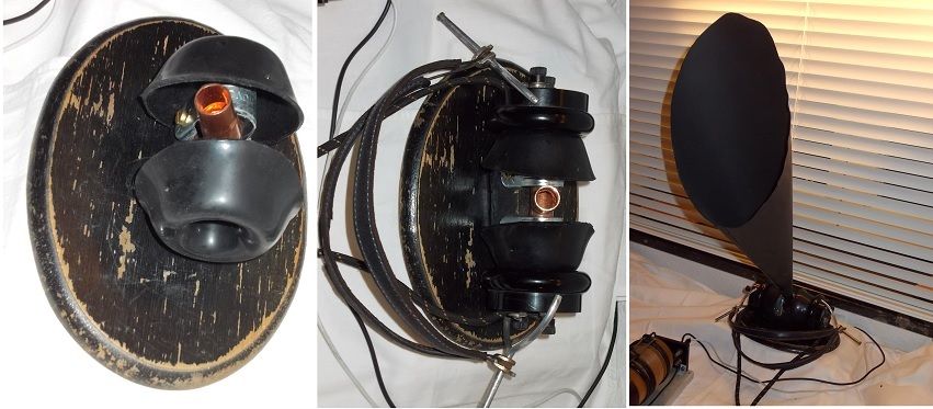
This is also the ideal device to be used in uncertain situations like the present one. (A pair of headphones costing sensibly less than a horn-loudspeaker) Another advantage is that if a sound is heard with such an improvised device, one can be sure to have good loud audition in a real horn-loudspeaker.
Finally I turned on the power and adjusting the controls, I got BBC 4 in Adapt-O-Phone, not very loud but comfortably intelligible. I placed HERE a link to the clip illustrating the event.
So, it seems that the second stage works properly too, in spite of my compulsory lowering the interstage transformer ratio and using an improper valve in the final stage. On top of everything, I used only 45 VDC as anode voltage: The screen grid of 2Ж27Л does not allow more than that. (At least in theory).
Increasing Output Power
I manufactured an adapter for 4П1Л wired as a pentode using a Loktal socket and a home-brewed B5 plug. Both filaments were connected in parallel so I could use the same heating (2 X 1.2 VDC D size accumulators).

The previous user has already marked, in pencil on the chassis, the polarity of the bias battery. By drawing the circuit diagram I checked and the markings made sense. In fact these markings gave me the confirmation that the middle B 5 valve socket was not meant to receive a valve, but a plug of some kind for the bias battery. Using two adapter plugs I accordingly wired the terminals of a battery clip containing 2 X 1.5 VDC AA size batteries:
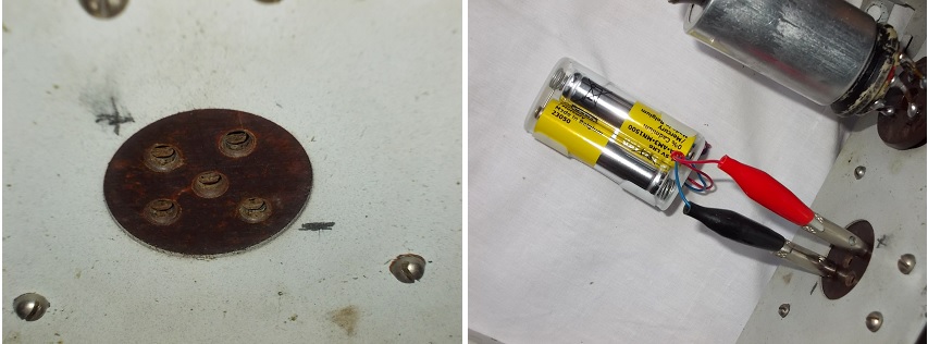
I turned on the set enjoying an increased sound level and the dull glowing of the filament inside the final pentode:

Soon I decided to add another 45 VDC to the anode battery. The volume increased, but now I could hear small distortions by the forte music passages and very loud speech. According to specifications, 4П1Л should have a first grid negative bias between 4.5 and 9 VDC and I was using only 3 VDC. I found an adapter which could accommodate 3 X 1.5 VDC “AAA” batteries and I connected it to bias the final stage:

Now the signal is loud and clear.
The “Gramophone” input
While operating as a receiver, the first stage is a regenerative detector in the upper bend of the triode and it is biased accordingly. Although I do not grasp (yet) all the reasons which made the set designer choose the voltage divider solution for biasing, I must admit it is serving the purpose.
To use the first stage as an audio frequency amplifier, the valve should be biased to work in the middle of the linear characteristic, that is, to receive a more negative biasing voltage on the grid. This is accomplished by leading the return connection from the gramophone input to one of the pins of the middle valve socket clearly meant to receive some sort of plug bringing biasing voltage.
It is obvious to me that the bias battery was meant to have taps and by operating the set with the original valve (HL2) the gramophone return should have been connected to – 1½ or – 3 VDC tap of the bias battery. Since I operate the set with a 2Ж27Л wired as a triode I connected the gramophone return to the ground.
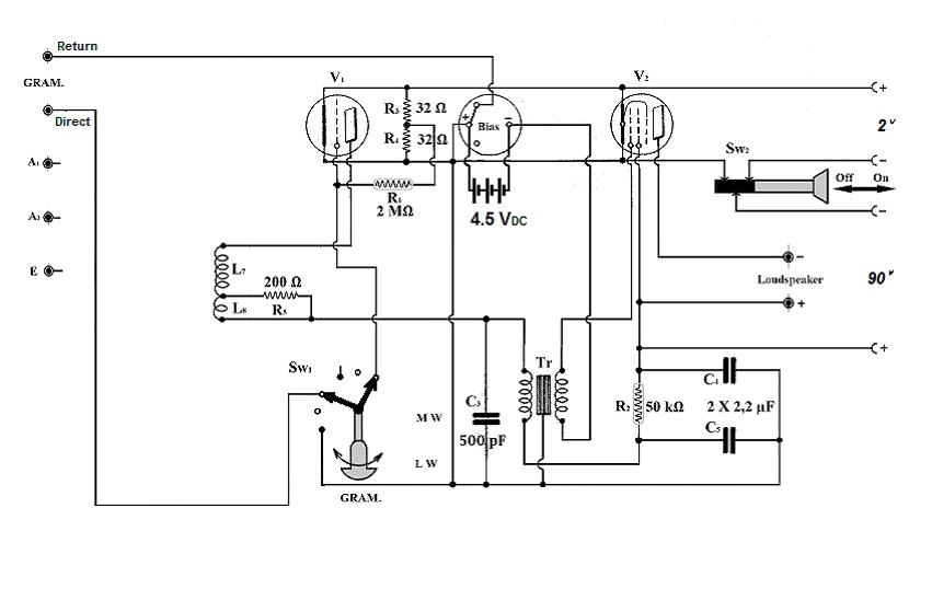
I was anxious to test the set as a plain audio frequency amplifier using the gramophone input, having in mind that I had to reduce the ratio of the interstage transformer and I equipped the set with Russian valves.
I connected an audio frequency generator (G) at the gramophone (GRAM.) input, I put the switch (Sw1) in the proper position, and at the output I connected a resistive load (RL) of 2.2 kΩ (5 W):

An electronic voltmeter (mVAC) is reading the alternate voltage on the load and the voltmeter output is fed into a very plain oscilloscope (Osc.).
Using 4П1Л as an output pentode, one can inject up to 100 mVAC 1000 Hz signal obtaining 15,5 VAC on the load, without any noticeable distortion of the sinusoid on the scope. (Under 10 %). I used the opportunity to confirm the choice of the bias voltage (- 4.5 VDC) by increasing the input AC voltage and monitoring the symmetrical limitation of the signal on the scope. The overall voltage gain reaches 36 dB and maximum output power 110 mW. The frequency range at – 3 dB goes from 150 to 15 700 Hz. (Not bad at all considering the improvised interstage transformer.) The set not being screened I didn’t bother to measure signal-to-noise ratio.
Using 2Ж27Л as an output pentode, one can inject up to 100 mVAC 1000 Hz signal obtaining only 5 VAC on the load, without any noticeable distortion of the sinusoid on the scope. (Under 10 %). Since 2Ж27Л specifications indicate 0 VDC bias voltage I replaced the bias battery with a simple connection between + and – bias. The overall voltage gain reaches 26 dB and maximum output power 11 mW. The frequency range at – 3 dB stays the same.
The L8 Coil
Working with the set I discovered another fault: the one-turn-coil L8 was interrupted. The resistor R5 connected across it, (to me it looks of a more modern making), is most probably a later and cheap work-around solution to restore the set’s functionality. I took L8 out in order to repair it and I found out it wasn’t an ordinary wire but a very thin resistive wire wound on a core made of some 3-4 lengths of sewing cotton, everything double cotton covered:

The trouble is, it is interrupted on more than 2-3 places so I cannot possibly mend it and I have no idea (yet) what can I use to replace it. I was able to find at one end 16 uninterrupted millimetres which measured roughly 80 Ω so I concluded the resistivity distributed on the whole turn was (approximately) 1000 Ω. (The diameter of the tube being 63 mm, one turn should be about 200 mm.)
Hence, the receiver had originally a last resistive turn in tickler, positioned very close to the other “normal” turns. Whether this configuration did something to keep a steadier regeneration over the entire range as Mr. Wolfgang Holtmann suggested, remains to be proven. Using the set only with 200 Ω concentrated in one resistor soldered to the terminals of the interrupted L8 coil, I had to handle the regeneration control the usual way: while tuning higher frequencies I had to reduce the regenerative amount and vice versa. Until a proper replacement for this peculiar device is found it would be impossible to confirm or infirm Mr Holtmann’s supposition.
The first attempt to emulate a turn having a 1000 Ω distributed resistivity over a length of 200 mm was soldering in series 9 small 120 Ω resistors with terminals properly cut to cover the required length

Although I used ¼ W resistors they were too bulky to be squeezed in the original cover tube so I had to use a length of dark-brown shoe-lace which I impregnated with wax dissolved in petrol once my “resistive wire” was inside. After the petrol dried I put the new “L8” in place and tried the set:
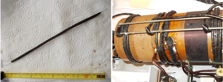
In comparison with the previous configuration (R5 = 200 Ω) the regeneration became steadier over the whole wavelengths range but still the set started howling as I tuned the upper third of the frequency range without touching the regeneration control.
*******
To be continued
Leverkusen
Started: 31.12.2016.
Best regards,
Pitagora Schorsch
Attachments:
- Pads (17 KB)
- Mettalic Grid (133 KB)
- Terminals (203 KB)
- Resistor 1 first (101 KB)
- Resistor 2 first (94 KB)
- Resistor 1 caps (46 KB)
- Resistor 1 back (111 KB)
- Divider in set (66 KB)
- Divider out (63 KB)
- Divider repaired and in place (106 KB)
- Block C old (87 KB)
- Block C empty (126 KB)
- Block C refilled (144 KB)
- Block C tar (102 KB)
- Interstage old (95 KB)
- Interstage bits and (72 KB)
- Interstage new wnd (53 KB)
- Interstage almost and (86 KB)
- Prepare Bananas Batterries (77 KB)
- Choose Headphones (111 KB)
- First Valve (106 KB)
- Test First Stage (75 KB)
- Final Valve Week (110 KB)
- Setup AdaptO (112 KB)
- Adapt O Phone (121 KB)
- Power Final Valve (129 KB)
- Bias 3 V (79 KB)
- Dull Emitter (90 KB)
- Bias 4V5 (111 KB)
- Circuit Diagram 2V (85 KB)
- Circuit Diagram GRAM (69 KB)
- Measuring Diagram (54 KB)
- L 8 A (93 KB)
- L 8 B (64 KB)
- L 8 C (123 KB)
To thank the Author because you find the post helpful or well done.