Measuring the terminal impedance of random wire antennas
Measuring the terminal impedance of random wire antennas

The most common type of antenna used with AM broadcast (North America and Europe) and LF broadcast (Europe only) band receivers is the electrically short random wire antenna where the total length of the antenna wire does not exceed lambda/10 of the highest reception frequency. In ideal setups, the antenna wire is strung from the room containing the receiver through the window or another opening in the building's walls to a support post outside the building. In less ideal setups, the antenna wire simply runs along the (inside) walls of an apartment.
Unlike magnetic loop antennas, random wire antennas need a ground connection to function properly. The ground connection serves as one of the two terminals of the antenna while one end of the random wire is the other terminal. In ideal setups, this ground connection is provided by a grounding rod driven deep into the soil near the antenna wire. In many other setups, however, the water or central heating plumbing is used as a ground connection. If no decent ground connection is available at all, a
counterpoise wire stretching away from the antenna wire can be used.
The impedance of such electrically short antennas is (approximately) composed of a capacitive reactance CA in series with a loss resistance RA, resulting in the following Thevenin equivalent circuit:

The losses in outdoor random wire antennas occur mostly due to imperfect grounding while wire and radiation resistance are neglectable. The reader is referred to this article for a more in depth discussion of losses in electrically short antennas. At this point, the desire to measure the capacitance and loss resistance of actual random wire antenna setups might arise. After all, calculating the impedance of the electrically short random wire antenna from formulas is only feasible in very simple setups where a perfect ground connection is assumed and the soil is treated as a perfect electric conductor (PEC). The task of experimentally determining the antenna's impedance can, of course, be accomplished by using commercially available network analyzers. However, due to their expensiveness, only very few vintage radio hobbyists will have access to such a device.
An alternate method that might come to mind is to connect an inductor with a known inductance across the terminals of the antenna, thereby creating a tuned circuit with the antenna's capacitance CA acting as the capacitor and the antenna's resistance RA accounting for the losses. Of course, the inductance needs to be chosen such that the resonant frequency is within the intended frequency range of the antenna. This antenna tank could then be driven by an inductively coupled signal generator. Furthermore, an oscilloscope could be connected across the antenna's terminals, parallel to the inductor to measure the voltage at the antenna tank. Then, the antenna's capacitance CA could easily be determined by the resonant frequency of the antenna tank and the antenna's loss resistance RA would be given by the Q-factor of the antenna tank that could in turn be determined from it's bandwidth.
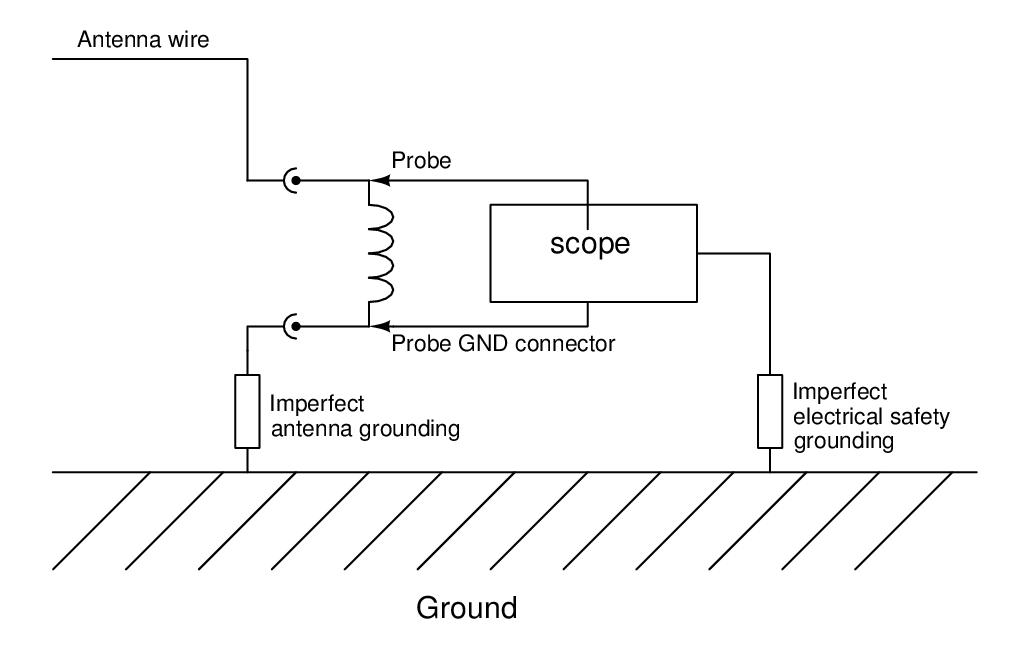
However, this approach has a fundamental flaw that becomes obvious when looking at the setup more closely:

Obviously, the electrical safety grounding of the oscilloscope provides an alternate (and also imperfect) path to ground that is connected in parallel to the existing path to ground thereby altering the entire setup and the results of the measurement significantly. It needs to be pointed out that operating the oscilloscope without the electrical safety ground connection is not only potentially dangerous but will also not solve the problem. That is simply because the chassis of the oscilloscope will act as a counterpoise ground to the antenna wire.
One solution would be to use a (typically expensive) battery powered oscilloscope with fully symmetric signal input. There is, however, a much more inexpensive method that requires only regular, mains powered and grounded devices. This method shall now be presented:
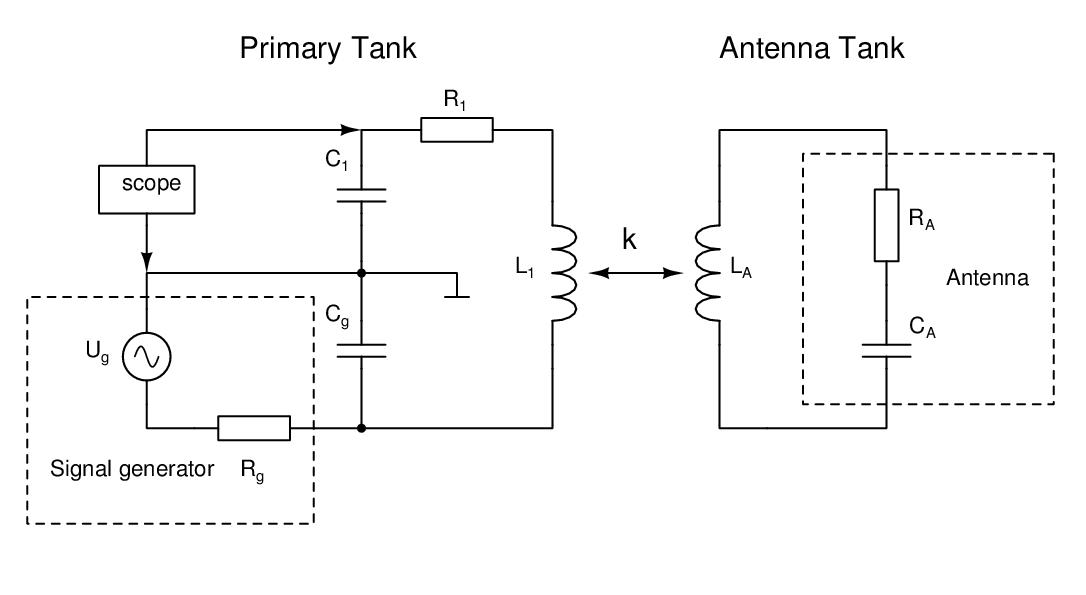
We will make use of a tuned transformer setup where the signal input and output is done on the primary side and the secondary side is made up of the antenna tank i.e. the antenna with an inductor connected to it's terminals. This setup is shown in the following diagram.

The input voltage from the signal generator is fed into the primary tank by a large shunt capacitor Cg to avoid the primary tank being loaded by the low output impedance of the signal generator of usually 50Ω. In this setup here, a typical ratio is Cg/C1=1000. The output voltage is the voltage across the capacitor C1. A detailed analysis of the circuit can be found in the PDF document attached to this article.
It is advisable to set the output level of the signal generator as high a possible to overcome the inevitable voltage pickup by the antenna. Also, the resonant frequency of the tanks should be set at a relatively quiet frequency within the intended reception frequency range of the antenna.
As it turns out, this version of the tuned transformer also exhibits the familiar double humped frequency response curve if the inductive coupling factor k between the inductors is above a certain threshold as can be seen from the following plot:

Note that in this case, the slight lopsidedness of the frequency response curve is expected. See the attached PDF document for more details.
Theoretically, the impedance of the antenna connected to the secondary side could be calculated from the shape of the frequency response curve appearing on the primary side. However, this would entail using rather long and cumbersome formulas and require highly accurate measurements of various parameters such as the coupling factor that are difficult to make. Therefore, a simple experimental approach is preferable: We'll disconnect the antenna from the secondary side and replace it by a resistor in series with a capacitor. The values of the resistor and the capacitor are chosen such that the influence on the frequency response curve at the primary side is the same as with the actual antenna connected. In other words: While in most cases an equivalent circuit is used in simulations and calculations, here we'll actually build one in hardware!
The following conclusions reached in the detailed circuit analysis will help us to devise a strategy to quickly and straight-forwardly figure out the correct values of the resistor and capacitor:
- If the resonant frequency of the secondary (antenna) side is above the resonant frequency of the primary side, increasing the coupling factor k between the inductors will push the resonance peak of the primary side towards lower frequencies.
- If the resonant frequency of the secondary (antenna) side is below the resonant frequency of the primary side, increasing the coupling factor k between the inductors will push the resonance peak of the primary side towards higher frequencies.
- If the resonant frequencies of the two tanks are identical, increasing the coupling factor k between the inductors will deform the single peak curve into the familiar double-humped curve with the center dip being where the single peak used to be. Note that a slight lopsidedness of the curves is expected.
- The lower the loss resistance RA at the secondary side, the deeper the center dip will be at a given, sufficiently large coupling factor k of the inductors.
From the above conclusions the following strategy for experimentally determining RA and CA can be deduced. Note that at least one of the inductors needs to be adjustable e.g. by a ferrite slug.
We will start with the two inductors set to the same value. The primary side capacitor C1 is chosen to be of the same magnitude as the antenna capacitance CA (typically in the 30pF-300pF range) and the resonance curve of the unperturbed primary side (k=0) is displayed on the oscilloscope by setting the signal generator into frequency sweep mode. Now, the inductive coupling factor k is increased (this is easily accomplished by moving the two inductors closer together) and the influence of the secondary side on the resonance curve of the primary side is observed. Bearing conclusions 1 and 2 in mind, we can easily select C1 from the range of standard values so that it roughly matches CA. After doing so, we will use the ferrite slugs in the inductors to exactly match the resonant frequencies according to conclusion 3.
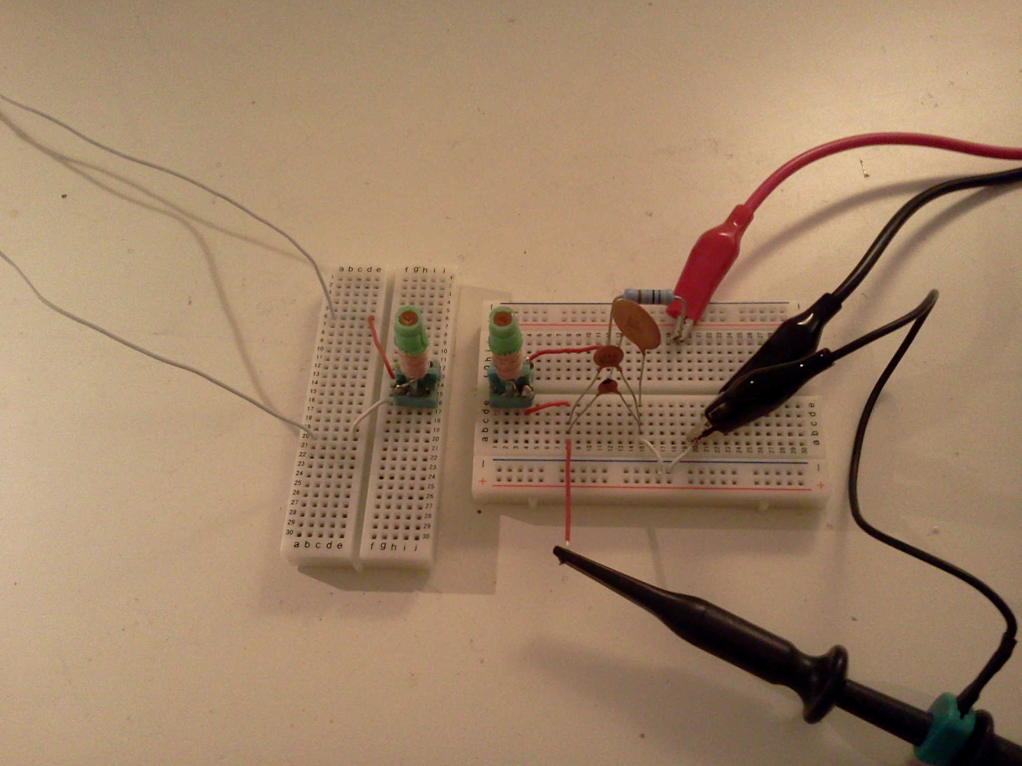
The picture below shows a setup where the primary and secondary side have been built on two breadboards that can be moved against each other. This provides an easy way to alter the coupling factor k between the inductors. Note that the input capacitance of the oscilloscope probe adds to C1.

After matching the resonant frequencies of the primary and secondary (antenna) tank, we'll choose an inductive coupling factor k=k0 such that a double humped curve with a pronounced center dip occurs. The amplitude A0 at the center dip should be about half the amplitude of the two peaks. We need to note the exact value of A0. We do not need to obtain the numeric value of k0. However, we need to be able to exactly recreate this specific coupling factor which can easily be accomplished by recreating the exact relative position of the inductors. In the setup depicted above k0 is set by aligning the two coils with the breadboards touching.
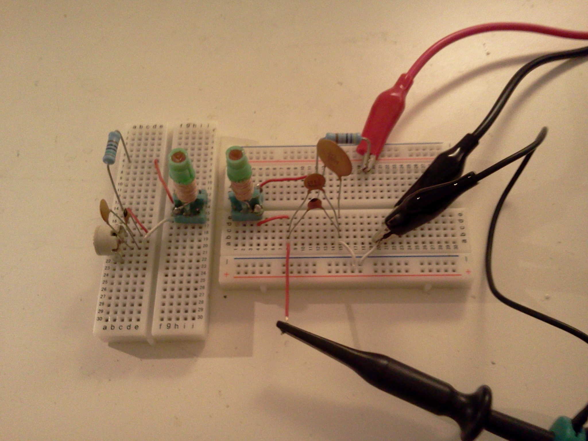
Now that we have matched the frequencies of the primary and secondary (antenna) tank and being able to easily recreate the inductive coupling factor k0 between the two tanks, we are ready to remove the antenna leads and replace the antenna with a variable resistor RA and variable capacitor CA in series. The initial value of CA is chosen to be roughly the same as C1 and a good starting point for the loss resistor RA is 100Ω which is the typical magnitude of random wire antenna losses. In practice, it is convenient to use fixed value capacitors in parallel with trimmer capacitors and fixed value resistors in parallel with trimmer resistors. Such a setup is shown in the following picture.

First, we'll determine CA to match the capacitance of the antenna. By varying the inductive coupling factor k we can see whether the secondary tank's resonant frequency is below, above or equal to the resonant frequency of the primary tank according to conclusions 1,2 and 3. Setting CA such that the resonant frequencies of the tanks are equal again and measuring it's value then yields the antenna's capacitance.
It should be noted that trying to measure the antenna's capacitance with an LC-meter using a quasi-static measurement method will in many instances produce bogus results since the voltage picked up by the antenna from external sources (radio stations, mains hum, ...) will interfere with the measurement process. However, the capacitance CA of the capacitor in the equivalent circuit can, of course, be measured with an LC-meter.
Second, we'll determine RA to match the loss resistance of the antenna. To do so, we first need to recreate the inductive coupling factor k0 between the inductors as described above. Bearing conclusion 4 in mind, we can then vary RA to recreate the same amplitude A0 of the center dip that was produced by the antenna. Measuring RA then yields the antenna's loss resistance.
Attachments:
- Detailed circuit analysis (146 KB)
To thank the Author because you find the post helpful or well done.