Modulation Depth of Today's Broadcast Band
Modulation Depth of Today's Broadcast Band

Dear Friends:
I am restoring an early superhet with the following tube lineup: 6D6 6D6 6C6 6F6 and 5Y3 rectifier. The first 6D6 works as an oscilator / mixer (no pentagrid converter on this radio) and the 6C6 is working as a plate characteristic detector (no diode!).
The radio was a basket case with an open coil and many loose connections, including several wrong ones (looks like a previous attempt to fix the radio) Initially I thought the IF was 175Khz but after alignment I discovered that it seems to be 190Khz, which makes it the first radio I work on with this IF. I decided it was an interesting radio to restore and draw a schematic of the few connections that were left and came up with a new schematic based on similar radios. I used this to re-mount the entire set. Thank you to Bill Meacham for his help on this.
The question is the following: the audio is a little distorted, it gets worse in some stations and it is not so bad in others. I spent several days trying to troubleshoot this but could find no answer. Swapped tubes, re-routed cables, changed speaker and output transformer but all to no avail. I now this type of detection is supposed to have more distortion but even so, this was more than acceptable.
Talking with Heriberto and some other friends, we concluded one possible answer could be the modulation depth used nowadays. BCB stations in Buenos Aires seem to be using a modulation that is close to 100% and what gave me the hint is the fact that I have seen this problem before in some old regens I have.
Not wanting to give up, I changed the 6C6 for a 75 and modified the connections to turn the radio into a "diode detector" and voila! Audio is now crisp and clear!
I cannot think of a better explanation to this. I am not sure whether I should leave the radio as it is or put it back the way it was so it is "original".
Can anyone tell me if modulation depth is the cause of this problem? Have you seen it in your area? Any recommendations to deal with this problem? Thanks
Mario
To thank the Author because you find the post helpful or well done.
Nowadays Modulation Depth about 95%

nowadays modulation depth is about 95%. In the beginning of radio days, for technical reasons this figure was 30% to 50%. The limiting factors were the modulator of the transmitter as well as the demodulator (or detector) of the receiver.
Audions and plate detectors only will process 60% to 70% modulation depth with acceptable distortion.
Additionally, nowadays audio signal processing (e.g. Optimod) reduces the dynamic range of the audio signal substantially. Therefore the mean value of the modulation depth is distinctly higher than in it was formerly.
Your question is a good opportunity to complete my skript on AM demodulation.
Best regards,
Dietmar
To thank the Author because you find the post helpful or well done.
Modulation depth

My knowledge is not sufficient to know if over modulation gives the same distortion effect as a high signal level from powerful local stations. I have seen this effect on several radios, both valve and transistor. On one of my portable transistor sets, which can also be used as a car radio, switching out the internal ferrite antenna so that the input connects to the antenna socket only (with no antenna connected), removes the distortion, suggesting that signal overload is the problem. What do others think?
William.
To thank the Author because you find the post helpful or well done.

Thank you Dietmar and William.
I am sure now that Dietmar's explanation is the right answer. William: I thought about overloading but since the set did pick up some stations with a 20cm antenna I had to discard that idea, the signal level was too low for overload.
I also have a tube signal generator and I am sure its modulation depth is not beyond 50% or 60% because of the type of circuit it uses. While aligning the radio with this signal generator I noticed the audio tone (400Hz) was loud and clear on the speaker.
Now the question is: what can we do about this? Of course one can use an AM transmitter in which the modulation depth can be controlled so as not to go beyond the limit, but is there any other way? For now, I think I will keep the 75 tube in there and convert the radio to diode-detection. Hate to modify the original circuit but after all it is probably a kit radio and it is not usable with the plate detection.
Thank you again
Mario
To thank the Author because you find the post helpful or well done.
"I am sure now that Dietmar's explanation is the right answer."
Dietmar is correct.
"I also have a tube signal generator and I am sure its modulation depth is not beyond 50% or 60% because of the type of circuit it uses."
Most "vinatage" signal generators will not go beyond 75% modulation.
"Now the question is: what can we do about this?"
You might consider going back to the 6C6 and wire it as a audio preamplifier instead of a plate detector, and use a germanium diode such as a 1N270 as the diode detector under the chassis. As they say, out of sight, out of mind.
We have similar problems with '50s vintage German radios trying to cope with todays FM modulation capabilites.
Jeff
Edit: removed frame in order to have the whole text legible. MH
To thank the Author because you find the post helpful or well done.

It is a good idea though and I might go back to it if all else fails. My question was a little vague so let me rephrase it: can we somehow improve the plate detection method so as to make it work with 90% modulation depth? Could grid detection be improved also?
I will go back to my books and see what we can find.
Thank you all for the wonderful responses!
Mario
To thank the Author because you find the post helpful or well done.
Distortion Factors of Detectors

- carrier amplitudes
- modulation depth m
- detector characteristics
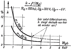
Distortion factors k become smaller when carrier amplitude increases (right figure). Additionally, distortion factors k get bigger when the modulation depth m increases.


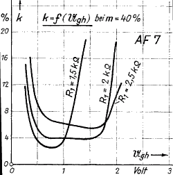
The figure on the right hand side shows similar graphs for a penthode (AF 7) as a plate detector. Here the characteristics additionally depend on the value of the cathode resistor R_1.
If the tubes are used as grid detectors, the values of optimal carrier amplitudes are lower and the range for small distortion factors is very narrow.


(figures 2 - 6: Kammerloher, Hochfrequenztechnik 3, Gleichrichter, Wintersche Verlagshandlung, 1957)
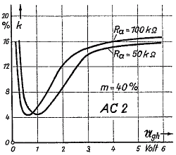
Whereas k decreases for increasing carrier amplitude in the case of diode detectors, plate detectors and (much more) grid detectors only have a limited amplitude range where distortion factors become halfway small.
Additionally distortion factors depend on the modulation depth m. As the graphs show, m=40% was a usual value at former radio days.
However, AM bandwidth is limited to 9 KHz (region 1), which gives 4.5 KHz audio bandwidth. This sounds quite muffled. A distortion factor of a few percent then produces a higher pitch of the demodulated signal which therefore can be accepted.
Best regards,
Dietmar
To thank the Author because you find the post helpful or well done.

Mario
To thank the Author because you find the post helpful or well done.

Is there something that can be done to improve the output sound, however? Or is this type of distortion unavoidable with plate detection and deep (modern) modulation?
I have built by myself a nice TRF receiver last year, and have experienced the referred distortion as well. I thought it was caused by an inappropriate output tube / output transformer matching, or by wrong biasing somewhere in the circut. I have tried to introduce little retouches to the circuit, with no success (that's obvious, as I didn't even consider the plate detection as source of the problem).
Something else that can be done?
To thank the Author because you find the post helpful or well done.

Marco: if it's a grid type detector then you can play with the series resistor, the lower you go the less sensitivity you will get, but also the audio gets better. Now in plate detection there is not much you can do, because changing the signal level will not change the modulation depth, however, I am experimenting to see whether we can get good results by changing the working point on the tube, will let you know what I find.
the best option if you are building a homebrew like the TRF you describe, is to use diode detection and to do this you have countless tubes you can use.
Many TRF in Argentina used the 75 tube as a combined diode detector / amplifier, and I have some circuits you can try if you want.
Adios!
Mario
To thank the Author because you find the post helpful or well done.
Modulation depth today indeed is close to 100%, with rigourous processing, to avoid the noise in AM reception.
A new trick is over 100% positive peak modulation, now the neg and pos parts of the audio signal are seperated and get different amplitudes.
A 100% modulated signal would mean 4 x P-carrier at positive peak, the FCC allows 125% pos peak mod. In Europe there are no rules, and modern TX's can go as far as 145 % pos peak.
This does introduce distortion on some radio-receivers.
This high mod process is used by the broadcaster to overcome noise and be loud in the band. It also saves energy to reduce carrier power and increase modulation with more or less the same reception results.
To thank the Author because you find the post helpful or well done.