Old capacitor markings

ID: 153037
Old capacitor markings 
15.Nov.07 23:00
0

Lars-G. Lundelin (FIN)
Articles: 143
Count of Thanks: 4

Hello Radiofriends! In my recent project with an ancient TRF radio set I found that a variable capacitor,presumably the volume control, has been destroyed for some reason. There's no printed value markings only three coloured dots, (Red Green and Yellow) see the attched pictures. Might it be a value indication or not? I replaced the variable cap with a 200 pF silver mica and the set works quite well, but no control of volume. Even three other capacitors where replaced with the markings 200 cm 2000 cm and 100000 cm. I understand these values are in pF but what does the "cm" standing for? The second picture shows the plate shapes and there are seven of each. regards Lars-G. Attachments:

To thank the Author because you find the post helpful or well done.

 2
 
16.Nov.07 01:36

Martin Renz (D)
Officer
Articles: 694
Count of Thanks: 16
Martin Renz

Hello Lars-G.
cm was used until the 40ies of the last century
1cm = 0,0885pF*4π ≈ 1,1pF

You can read more about it here and in this thread, unfortunately in German.

To thank the Author because you find the post helpful or well done.

 3
Capacitance unit 
16.Nov.07 12:46

Lars-G. Lundelin (FIN)
Articles: 143
Count of Thanks: 8

Hi Martin! Thanks a lot for your information.This capacitance unit was a new planet on my starry sky. I looked at the informative thread and with a little help of a dictionary I think I can find out what's it all about. regards Lars-G

To thank the Author because you find the post helpful or well done.

 4
Scratching my head... 
16.Nov.07 16:57

Todd Stackhouse (USA)
Articles: 151
Count of Thanks: 8

...this is the first time I have ever heard of a variable capacitor used as a volume control!  The colored dots, if they are a value marking, suggest a value of 250 000 cm (?--also, the first time I ever heard of cm as a unit of capacitance!...), but, at 275 000pF (275nF), this seems very large for a variable capacitor, even one of that physical size...so, perhaps the yellow dot was not a multiplier?...in which case you're looking at 254 cm (approx 280pF).  (red=2, green=5, yellow=4 or 104)

...just educated guessing on my part...I am just an ignorant American, after all ;>)...


To thank the Author because you find the post helpful or well done.

 5
Vintage Volume Control 
19.Nov.07 16:25

Dietmar Rudolph † 6.1.22 (D)
Articles: 2492
Count of Thanks: 14
Dietmar Rudolph † 6.1.22

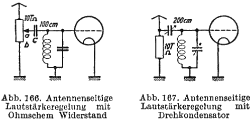
In the beginning of tube radios, no variable mu valves were available. Therefore, other methods of volume control were usual, and some of them now appear to be rather odd, like volume control with a variable capacitor. Early radios often were regenerative audions. The amplification factor of these sets was moderate, so it was possible to contol their volume with the aid of the antenna voltage. This could be done with a potentiometre or a variable condensor. Figures 166 and 167 show these methods. (10 TΩ = 10 kΩ; T means thousand)
Volume Control with Potentiometre and Variable Condenser

A similar method was the control with a variable inductive coupling or a shunt potentiometre in parallel to the antenna coil, Figures 168 and 169.
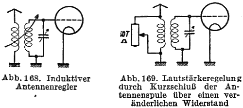
The variable capacity and the variable inductive coupling change the resonance frequency of the receiving LC circuit. Therefore, re-tunig was necessary especially if the bandwith was narrow, due to regeneration. An improvement then was a differential variable capacitor. The resultant capacity for the tuned circuit remained constant irrespective of the actual antenna coupling, Fig. 170.

      
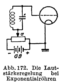
When variable mu tubes (exponetial tubes) were available, volume control could be made by changing the grid voltage of these tubes, fig. 172. In the early '30es this had to be done manually until automatic volume control (AVC) had been invented.

[Günther, H.; Richter, H.: "Schule des Funktechnikers", Vol 1, Frankh, Stuttgart, 1939]

From the schematics can be seen that the value of the variable antenna capacitor  is  approximately 200 pF and so of a value comparative to the capacity of the antenna itself. The 3 coloured dots on the condensor in the photo in post 1 obviously are no coding of the capacitance value.

Best regards DR

To thank the Author because you find the post helpful or well done.

Thread locked Thread closed by a moderator. But replies can be made through a moderator.