philco: 80B detector bias
philco: 80B detector bias

Fellow Radiophiles,
I own a Philco 80B Junior in the cathedral case with the simple flat front.
This radio only had two simple problems. One was sudden changes in the level of regeneration, and the other was too much detector distortion.
The sudden changes in regeneration were caused by dirty chassis ground connections at the screws that hold the molded bakelite single and double capacitor units. The application of DeOxit contact cleaner from CAIG laboratories to the screws, while loosening and tightening them, eliminated the unstable regeneration problem. As a preventive measure, I also touched up with DeOxit every grounded riveted at the tube sockets, along with the socket contacts, and any other contact I found, including the sliding contacts of the dual gang tuning capacitor. The operation is now very reliable.
The remaining problem was the excessive distortion at the detector grid. This radio has only one stage of gain provided by the type 36 tetrode used as a self-oscillating superheterodyne frequency converter, before the detector grid of the second type 36 tetrode working as a regenerative grid-leak detector.
Under these conditions, the signal level presented to the grid, is often not larger than the built-in contact potential around -0.7V that appears at the grid that is caused by the space charge surrounding the cathode. Contrast this situration with the signal levels presented to the diode detector of a conventional superhet radio that has a separate IF gain stage, where the IF signal present to the detector diode is at least 0.5Vp-p. When there is a large signal, the detector operation is very linear because the relatvely large p-p amplitude makes the detector diode appear fully on or fully off during signal rectification.
At the usual small signal levels found at the input of regenerative detectors, the detection operation is quite non-linear for the small signal region under 100mV, and may become even worse for signals that operate partly in the small signal and large signal regions. All this just makes the DC bias point of the grid all the more critical to achieve reasonably low distortion over a wide operating range. One way to find the cleanest bias voltage is to experiment with different bias levels for a particular tube. These conditions change with tube age, as the negative contact potential that appears at the grid drops with reduced emission.
The following schematic shows the result of my experimentation with the bias level at the grid of regenerative grid leak detector in my Philco Junior 80B.
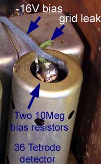
A 20Meg resistor made of two 10Meg resistors wired in series to the -16V grid bias source for the output tube, and soldered directly to the grid cap, provided distortion free operation for strong and weak signals. Keep in mind the signal strength is set by the volume control in the antenna circuit, so that the signal strenght presented to the detection grid is always the same for a given output volume.

The new old stock type 36 tube in the detector stage presented the following contact potential voltages under different load conditions, as measured with a Fluke 87III voltmeter with 10Meg input resistance in series with a 10Meg isolation resistor:
 -960mV with the 20Meg meter load and with the grid cap removed
-820mV when a 1Meg resistor was added, thus suggesting a grid inpedance around 160k at this voltage
-900mV when the 4Meg grid leak was reconnected with the grid cap, and the mid point of the two 10Meg grid leak resistors was grounded to kill the -16V bias source. This gives a total 2.5Meg load.
-1160mV with the 4Meg grid leak in place and the 20Meg bias to -16V. Calculating out the effect the 20Meg meter load, we get -1353mV, but that is assuming infinite grid impedance. The actual voltage should be somewhere between -1160mV and -1353mV
This final voltage is the current bias level at the grid. It was arrived at by listening for the least distortion and also by observing the least distortion of the audio signal driving the output stage. This point also gives the loudest volume and detection sensitivity, and the regeneration is not affected by signal amplitude.
The -1.2V bias is probably very near the unloaded contact potential voltage. Perhaps a slightly lower voltage might have worked better for very weak signals, but I was very satisfied with the operation I got from strong and weak stations.
A positive external bias source that forced the grid into a lower impedance region also gave very low distortion levels, but with greatly reduced volume.
A related thread dealing with the values of capacitance used in the grid leak circuit may be of interest too.
Regards,
-Joe
To thank the Author because you find the post helpful or well done.
Grid Current and Impedance measurement
Fellow Radiophiles,
After reading my own post, I was left wanting to know just what impedance levels at the 36 detector grid, made the operation so effective.
The grid cap is exposed at the top of tube, so no disassembly was necessary to measure the DC Voltage/Current characteristic of the grid. The screen grid was left biased as intended, with the 1Meg pull-up to 250V, which dropped about +13V at the screen under nominal control grid bias.
I disconnected the grid cap, and added a 1000pF capacitor bypass to the grid to reduce noise, then drove a variable power supply with the Fluke 87III wired in series to the sensitive uA input with a 10nA resolution.
 I swept the grid voltage from +300mV to -20V. This plot shows the zone near the detection point in detail. (click to enlarge)
The dashed Blue line is the load line for the 4Meg grid leak load resistor originally in the circuit.
The dashed Red line is the load line for the combination of the original 4Meg resistor with the 20Meg pulldown to the -16V bias source. It is the (Thevenin) equivalent of a 3.3Meg resistor wired directly to -2.7V.
These two lines are useful to find out at what bias point the grid was running originally, and with the new pull-down bias. Note that the original bias pulled 200nA from the grid, while the new pull down combination injects -500nA into the grid.
 A simple slope calculation of the previous curve yields the resistance plot shown here.
I was very surprised to see a logarithmic change of impedance as a function of applied voltage.
Note that the original 4Meg grounded grid leak biased the grid to a relatively low 140k impedance, while the new optimal bias point with the 4Meg in combination with 20Meg to -16V biased the grid to a 500k impedance.
While the output impedance of the IF transformer winding might have been somewhere around 100kOhms, it would have appeared much higher to the grid, once regeneration was applied. This explains the optimal bias point at 500kΩ.
This also explains the increased volume and sensitivity I got with the new bias point.
Last thoughts
Note that this 500kΩ bias point could not have been achieved simply by increasing the original Grid leak resistor value. Leaving the grid entirely open would have increased the bias voltage to just 790mV, and the grid impedance to no more than 200kΩ.
You might ask why was this bias point not done in the original design. One reason is that the grid characteristic would vary from tube to tube, and probably even more, as the tube aged, and the contact potential dropped. I expect that reduced emission in the 36 detector Tetrode will reduce the contact potential by several hundred mV, and probably completely silence the detector with the new bias point, as the impedance shoots up and eliminates rectification.
I may have obtained an optimal bias point, but this would not have been practical in the hands of the typical consumer. The 4Meg grid leak bias resistor wired directly to ground will age more gracefully, even if it was never optimal.
The sensitivity of the bias point also explains why there was so much fuss over grid leak resistors in the 1920's, when every small improvement mattered in one or two tube receivers.
Regards,
-Joe
Grid measurement data could be imported into a spreasheet or math program for further play:
mV uA
300 246
200 198.8
100 156
0 116
-100 76.7
-200 45.4
-300 23.78
-400 12
-500 6
-600 2.48
-700 0.71
-800 -0.09
-900 -0.4
-1000 -0.6
-1100 -0.67
-1300 -0.71
-1500 -0.75
-1750 -0.77
-2000 -0.82
-3000 -0.92
-4000 -0.96
-5000 -1
-6000 -1.03
-8000 -1.11
-10000 -1.14
-15000 -1.17
-20000 -1.18
To thank the Author because you find the post helpful or well done.