Schaub-Lorenz ,Kongress III
Schaub-Lorenz ,Kongress III

Dear collectors
I've a Schaub-Lorenz, model Kongress III.
This is a model similar to Kongress 53 shown in RM:
http://www.radiomuseum.org/dsp_modell.cfm?model_id=6058
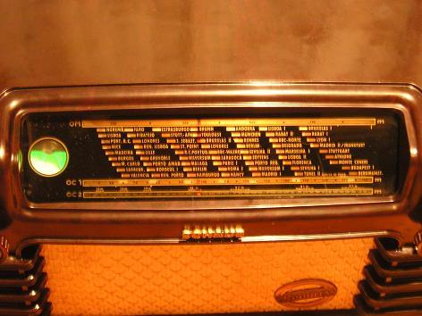
But, there is a visible difference. My Kongress III has one tuning indicator valve plus, not used in Kongress 53. Its reference is not visible.
Its mains power transformer is burned.
I need a schematic to repair it.
Can you help me?
Friendly regards
Mário
To thank the Author because you find the post helpful or well done.
Repair the Schaub Kongress 53

Hello Mario,
I have loadet the Diagramm for the Schaub Kongress 53 .
You can see, the Transformer use 20 or 30 Volt additional to the Powerline Voltage. In 1951 was this 220 Volt, now in Europa is the Standard 230 Volt. Wen you are using a' Silicon Diode i.e from the TV-Type, or 1N 4007, the needet Voltage of 260 Volt DC, will bee achieve.
You need then only a' 6,3Volt Heating Transformer.
In this case, dont forget to insert a' 15 to 22 Ohm Resistor in line to the Diode, to prevent Overloading during switching POWER "ON" .
I hoppe you agree?
Best regards from near Nuremberg Hans
To thank the Author because you find the post helpful or well done.
Schaub-Lorenz ,Kongress III
Thank you very much for your wise advices.
Yes. I saw your Schematic diagram. Before seeing I had not noticed that it was an auto-transformer. It is easier really, only a 230/6,3V transformer is needed, and the additional resistance, of course.
Nevertheless I have to rebuild the transformer, because I like to restore my radios keeping up the original design.
But I'll not forget to increase resistance to prevent those 10% voltage plus.
My 110V radios keep the original mains plug. They only switch on a 220/110V transformer plugged in a suiting socket.
Perhaps I have to make a 230/220V transformer for these special cases.
What do you think about that?
Best regards
Lisboa
Mário
PS: Now I took the transformer out from chassis I noticed that after all it is a normal iron cored transformer, galvanic isolated.
Maybe Kongress III is quite different from Kongress 53. Let's see what's going on next steps.
To thank the Author because you find the post helpful or well done.
Overvoltage on Radio?
Hello Mario,
You say: Nevertheless I have to rebuild the transformer, because I like to restore my radios keeping up the original design.
I see, you are one of the those collectors, the bring all Units in original condition.
All right, i am one off the technical performers. For me is important, that all Units working in original condition. Design on in- and out -site is not so important.
My 110V radios keep the original mains plug. They only switch on a 220/110V transformer plugged in a suiting socket. Perhaps I have to make a 230/220V transformer for these special cases.
What do you think about that? I recommend you, to make this in those manner.
Some Threats her in Forum in German and English (GB), include meanings about this Problem. <Tesla and UBL21 >
In my opinion, its to hard for old Radios to handle more then 10 % off the rated ( given from Factory ) Voltage!
O.K. Mario if you have additional questions, ask here!
Greetings from Hans
Oh! i see too late.
The Transformer can be for Export in a insolatet Version. Not all Countrys like the way to have no separtion between Line and Chassis!
To thank the Author because you find the post helpful or well done.
Old resistors symbols
I need help again. I would like to know the dissipation value for this 200 ohms resistor. Unfortunately I've not a table for those symbols.
Also I think that these 3x 16mF condensers are but 2 independent units - one 2x16mF unit and onother single 16mF unit-. Do you confirm?
Thank you in advance
Greetings from
Mario
To thank the Author because you find the post helpful or well done.
Resistors and capacitors

its the other Hans here :-)
one horizontal line in a resistor box means: 1/2 Watts
one cross ... means: 1/4 Watts
two rectangles in the corners means: 1/8 Watts
one vertical line means: 1 Watts
regarding you capacitors:
The schematics show three caps, possibly two of it are housed by just one cylinder, check the hardware and the wires.
Cheers
To thank the Author because you find the post helpful or well done.
Power - Dissipation of Resistors
Hello Mario, hello Mr.Kamann,
i agree with that was Mr. Kamann say.
To calculate der Power -Disipation of Resistors is very simple.
The Diagram shows, the Voltage across the Resistor is 9,5 Volt.
Power on a Resistor = Voltage x Voltage, divided by Ohms.
i.e. 9,5 x 9,5 / 200 = 0,45 Watt!
Greatings from Hans II
To thank the Author because you find the post helpful or well done.
Power supply system
Hello Dear Hans Kamann. Hello Hans Knoll
I'm very happy for your fellowship. Your knowledge and will helped me very much.
My Thanks to both.
This radio had some wires opened. The rectifier diode, some resistors and condensers were absent. It was a mass.
Now I've the burned transformer restored. The Schematic sent by Mr. Knoll and your replies helped me very much to rebuild the rectifier and power supply system. Thanks to Mr. Hans and Hans.:-)
Cheers and Greetings
from
Mário
To thank the Author because you find the post helpful or well done.
All clear!
Hello Mario,
i am glad, that all our Hints bring you to a good result.
Have a good Time here in our Community.
Regards from Franconia.
Hans M. Knoll
To thank the Author because you find the post helpful or well done.
Mains transformer heating
Hello Mr. Hans Knoll and Mr. Hans Kamann
Though the transformer is now repaired, the cause of heating had to be found because this "new" transformer had the same symptoms: it increased 30º C in 30 minutes.
I had to insulate and measure the main circuits. I measured 150mA from the 500 ohms resistor to the out-put transformer. On this transformer 1st coil was measured 350ohm (in C.C.) It was OK.
Looking to 6AQ5 tube socket there was a strange contact between pin 3 and pin 2.
After repairing, the current went down to 50mA. and the transfo doesn't go now up than 40ºC.
Also I changed the circuit form Kongress 53 to adjust it to a two coils transfo. Do you agree with it or are there any technical mistakes?
Best Regards from Lusitania
Mário
1st coil
Out-put 6AQ5
Transf Pin 6
To thank the Author because you find the post helpful or well done.
I change the Circuit, is allright?
Hallo Mario,
your results to the Power -Transformer are alright!
I think 30° C in 30 minutes to increases the Temp , maybe O.K.
Not good is the current from the 500Ohm to the Anode 6AQ5 you now that well.
Looking to 6AQ5 tube socket there was a strange contact between pin 3 and pin 2.
In consequence off this misconnection the BIAS of the 6AQ5 is shorted and the Anode current goes to dangerous Value for Transformer and Tube.
After repairing, the current went down to 50mA. and the transformer doesn't go now up than 40ºC
That's O.K. !
Also I changed the circuit form Kongress 53 to adjust it to a two coils transformer. Do you agree with it or are there any technical mistakes.
You due the right thing. Well!
One information for you: take care about the Power Consumption off the 6AQ5 . This type is a' bad Version fro the early 50tis.
Schaub and Lorenz alter there Models from 6AQ5 to the EL41.
The 6AQ5 has a' small Bulb and tend to have GAS and on succession a to high Current.
If you nor agree, please ask me.
Regards from Hans M. Knoll
To thank the Author because you find the post helpful or well done.
Nevertheless, where it cames from?
Here it is the finish "thing".
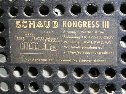
I wonder why the tuner indicator tube is not mentioned in the back cover label. The other 4 tubes are.
Where can I find any reference to this model?
By the way, here the temperature is too high. What is a safety temperature for a transformer like this one? It may rises 60ºC?
I apologize for so many questions.
Regards from Lissabon
Mário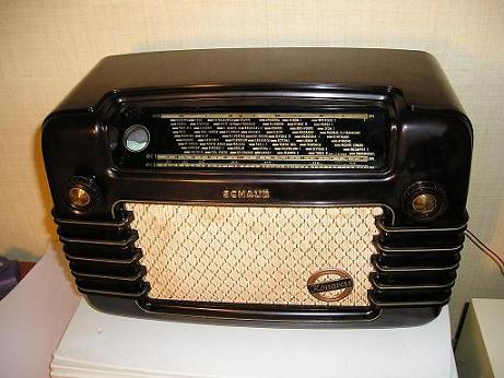
To thank the Author because you find the post helpful or well done.
Transformer to hot?
Hello Mario,
Your Question was:
By the way, here the temperature is too high. What is a safety temperature for a transformer like this one? It may rises 60ºC?
The German Safety Rules 0860 give the Ratings.


For normal Conditions ( Line -voltage= +10% over nominal [ e.g. 242Volts]) the Set must operating on a ambient Temperature between 15 and 35 °C
The temp. can increases round 55, 70 or 85°C above the Room - temp. depends from Type of material from insulation -Foil and Wire -insulation.
The lowest Value is 55°C + e.g. 25°C roomtemp. =
80°C absolute!
With better insulation = 110°C !
See Table VDE 0860
You can see under worst case the 60°C on your Radio is always O.K.
Your reserve is minimum 20°C.
That's what I can due for you. You agree?
wonder why the tuner indicator tube is not mentioned in the back cover label. The other 4 tubes are.
Where can I find any reference to this model?
For these Questions, I have no solutions!
Hans M. Knoll
To thank the Author because you find the post helpful or well done.
Late answer
I apologize not to had answered you earlier .
My answer was yes, of course. I agree with You .Now I know also ,thanks to You, the temperature was acceptable.
Thank you very much for your expertise and so greatly interested help.
Best Regards
Mário
To thank the Author because you find the post helpful or well done.
Finally
Hello Mario,
late, but not to late! This job is then closed,
let as go to "Schaub Goldy II P "
Today ( evening), I give you some information about this set.
Hans
To thank the Author because you find the post helpful or well done.