schneider: Romance FM 1961: Musing on Design
schneider: Romance FM 1961: Musing on Design
This is different from the 1958 Romance FM, but in the same case and using the same metal chassis including hole for unused EB91.
Schneider certainly did things differently
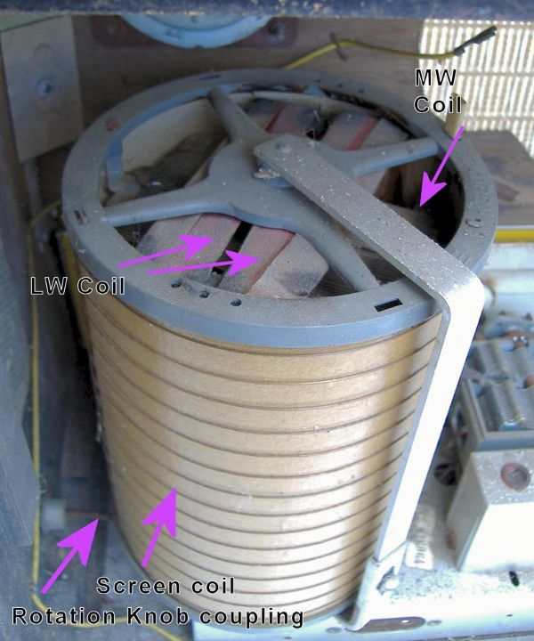
- Dual MW & LW loops at right angles in a drum with 3rd screen loop. Turned by knob on side of set
- 6AU6 + EL84 O/P (1958 version Romance FM uses 6AQ5 rather than EL84)
- Dual 1M gang pot for volume part of tone network
- ECF82 VHF-FM Head (1958 version Romance FM uses ECC85)
- 6.75MHz rather than 6.5 or 10.7 for FM IF
- No Schneider schematic shows the switch unit wiring and L.O. coils, just a box labelled "Bloc"
- EBF89 is FM detector and 2 x OA79 for AM Audio and AGC ((1958 version Romance FM uses EB91 instead of 2 x OA79)
- One combo AM & FM IFT can, but separate AM & FM IFTs elsewhere
- An "extra" FM IFT (6.75MHz) that looks like a low pass filter between IFT on o/p of ECL82 Pentode(the mixer) and the ECH81 Hexode used as a 6.75MHz IF on FM but mixer on AM (that's normal, it's the extra IFT that is unusual with tuning access only on bottom, closed top), despite looking like a LPF it peaks on 6.75MHz
- Entire VHF-FM dial is about + & - 50KHz fine tuning on SW band. Done with an extra variable coil inside the VHF head but only connecting to HF band L.O. on the main chassis ECH81
Tube line up
The Magic Eye is EM81
ECF82, ECH81, EBF89, 6AU6, EL84 and an EZ80 or EZ81. This was based on studying Schneider circuits, logical deduction and plain guess / trial (ECC85 tried then ECF82 for VHF head).
Schneider seem to especially like EBF89 (IF + Detectors) and 6AU6 (RF Pentode used as AF preamp) combo which doesn't seem common?
Audio stages of 1958 version of Romance FM
.png)
A comment made to me:
I've never seen NFB to the screen grid before! Also, the 6AU6 appears to be operating without any bias (the cathode is grounded and so, indirectly, is the grid).
The 6AU6 = EF94 and is about -1V or less vs -2V to 3V for EF93, EF95. I tested the EF93, 6AU6, an actual EF94, EF95 and E95F on the VCM163. The anode current is very sensitive to g2 volts. So at 0V Vgk with a low screen (g2) the Anode current can be "normal". Note the g2 is fed from anode but with AC decoupled
Bright orange is main HT
Orange is secondary HT filtered by 2k2 and 2nd capacitor
Brown is DC feedback from 6AU6 anode to g2
This shows that there is
1) Essentially DC feedback from Anode to g2 of 6AU6
2) AC feedback via tone control to g2 AND g1 from output at the speaker. The version I have is EL84, but circuit looks similar. Except it has Treble and Bass.
The Schneider models using EL84 are similar
The above schematic is an edited version of a different Schneider that uses dual gang pot for volume and 6AU6 + EL84. But it's not the same, hence I "greyed out" part.
Dual gang pot for Mono Volume Control
A comment made to me:
The dual gang pot looks like it has been fitted as an alternative to a tapped loudness control.
It's a feature of almost all the Schneider designs 1956 to 1959 I looked at. It's not used the same way as most tapped pots. The 1st pot near panel is fed with Audio via a screened cable. It's wiper goes to "maximum" end of 2nd pot beside switch (directly on all schematics I have seen, but my set has a 1 K resistor). The minimum end of 2nd pot is fed from tone control network which has a Bass and Treble control and is fed from the EL84. The wiper feed 6AU6 grid via a capacitor on screened cable.

The volume control is somehow feed from a Bass & Treble control in a feedbank network as well as the input. The Bass & Treble work well.
As well as the two screens on the 1st pot "earthy end" there is a wire going to "earthy" part of tone control cable. So the Dual pot has 2 wires (one signal & 1 "earth" from tone feedback) and two screened cables.
it's not an arrangement I've seen. It's obviously a deliberate DESIGN time alternative to a tapped pot. I suppose a single gang 470K pot and the tone feedback and audio in both via 470K resistors to "top" of pot might work...
An apparently puzzling feature is that many Schneider schematics (1956 to 1958) show only one tone control even when a photo appears to show Treble and Bass. (Romance FM 1958)
However close examination reveals that the 2nd knob on the right of piano keys is labelled "Cadre" (= framework , i.e. Frame or loop aerial), a knob to rotate the loop aerial. My model (stamped 1961 on chassis and VHF head) has a slightly larger Schneider badge and the "Cadre" knob is at the side. The front knob to right of piano keys is in fact Treble, like on German sets.
Here is close up of the "drum"

The outer "screen" wire could be used to pickup local interference and "cancel" or as a sky wave aerial on HF, but I think it's just a screen to reduce local E field pickup by MW & LW coils.
PO (MW) & GO (LW) each have a "Cadre" and "Ant" pair of piano keys. OC (SW) and FM just have one key each. There are two families of "Romance",
AM only = "Romance"
AM + FM = "Romance FM"
To thank the Author because you find the post helpful or well done.