Servicing Telefunken FM radios with AFC
Servicing Telefunken FM radios with AFC

Recently, reading a forum article about a defective Telefunken Gavotte, I decided to service my Hymnus Stereo that in the past evidenced similar problems after few minutes of operation. At the start the sound coming from a FM station was warm and loud but, with the time, a noticeable distortion appeared and the signal decreased. For about five to ten minutes the station could be received adjusting the tuning again from time to time. Then the sound began to be wobbled with a period of about 2 sec. while some moderate distortion was present even moving the tuning knob back and forth. Usually in Telefunken radios the electrolytic capacitor indicated by Bernhard in his answer is located inside the metal can of the last IF transformer. Its replacement could be quite difficult if one is not aware of the trick suggested by Bernhard. Anyway even to add a new capacitor from the bottom of the IF can, I had to remove the chassis from the cabinet.

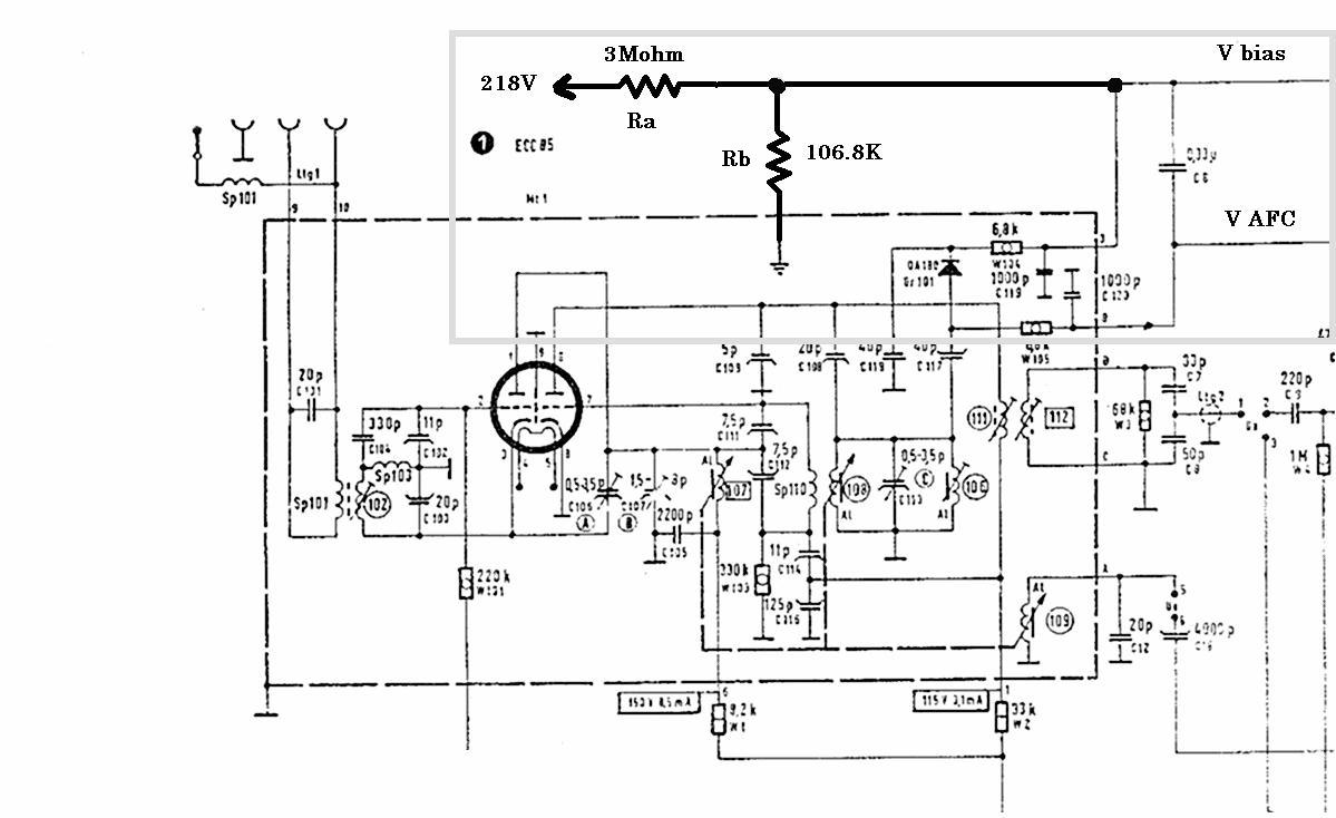
Eventually I decided to open the can and replace the old electrolytic capacitor. Since the power cord connector was riveted to the rear cover, I assembled again the radio before checking the result. What a surprise when I switched on the radio! The erratic behavior during the warm-up and the final distortion were still there. So I had to disassemble again the radio to perform a systematic fault tracing. At a first sight the AFC control loop could be responsible for the drift and maybe also for the low frequency sound wobbling after warm-up. Nevertheless, due to the unidirectional frequency drift during the warm-up and to the appreciable distortion at the end, I started checking the DC voltages. The bias voltage to the varactor in the AFC loop is actually derived from the anode supply through a voltage divider, referred to as Ra and Rb, in the simplified schematic below.
I monitored the plate voltage, Va, of one of the two EL84s as in the diagram below, referred to the left channel, during the warm-up.
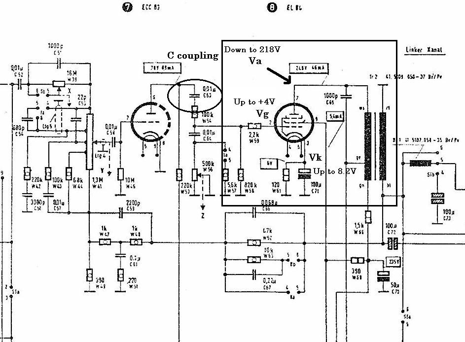
Starting from about 280V no load, in a few seconds the voltage dropped to about 250V, close to the nominal value of 248V. Then the reading became to slowly decrease to reach after some 10 minutes the final value of about 218V. In this condition, the voltmeter returned about +4V for Vg and about +8.2V for Vk. Bingo! The problem was all in the coupling capacitors between the preamplifier and the power stages. As one could expect from the average models of film capacitors, their leakage increased with temperature and the increased leakage drove the EL84s toward their saturation, so causing a further temperature increase and so on. The progressive increase in the current drain caused a drop in all the voltages generated from the B+ supply, including the bias of the AFC varactor.
Once replaced the coupling capacitors of the two power stages, the radio returned to its wonderful sound, locked on the selected station.
Intentionally I did not linked this note to the specific model, since it can be also applied to other radio models with similar AFC circuit.
To thank the Author because you find the post helpful or well done.
Nice writeup
Thanks Emilio, for a nice description of the problem. As I'm working on a couple of Telefunkens at the moment, it'll be something to keep in the back of my brain. I'll print this and keep in my Telefunken file.
To thank the Author because you find the post helpful or well done.