Simultaneous HF & LF Amplification
Simultaneous HF & LF Amplification

Simultaneous HF & LF Amplification
Some Further Observations
By P. G. A. H. Voigt.
(Member of the Wireless and Experimental Association)
Extracted from Wireless World May 27, 1922, Page 249-252
In a previous article on this subject, published in The Wireless World, on December 19th, 1921, I described several circuits by which valves could be used for “dual” amplification.
In this article, I wish to give improvements that eliminate most of the troubles experienced when working those circuits and give constructional details.
The first improvement is to decrease the number of adjustments by substituting for tuned HF transformers special aperiodic HF couplings, which, though less efficient, are more convenient to use.
This coupling is of choke capacity choke type and functions in the same way as the resistance capacity resistance coupling. It has, however, the advantage that this coupling is not necessary to use extra HT as in resistance coupling, and also strong signals cannot paralyse this circuit. The difference is that both anode resistance and grid leak are replaced by air core HF chokes with comparatively low ohmic resistance, so as not to diminish the LF transformer efficiency. To increase the HF efficiency the two chokes are closely coupled.
This electromagnetic coupling alone would be sufficient to transfer the HF voltages from the plate to the next grid or crystal in the cue of the longer waves, but for shortwave, the coupling condenser is required. The condenser need not exceed 0.00005 µF and when so small will not decrease the LF transformer efficiency. The chokes themselves are slab or basket coils with an inside diameter of about 4 cm and an outside diameter of about 9 cm. About 800 to 1,000 turns of 48 S.S.C. wire is sufficient for wavelengths up to 4,000 metres. If there are too many turns the circuit tends to whistle or howl.
The inner end of one choke should go to the plate and coupling condenser and the inner end of the choke should go to the grid and to the other side of the coupling condenser. The outer ends should go to the LF transformer and bypass condensers.
The efficiency of this coupling decreases when the wavelength decreases, just as in the case of resistance coupling, but if care is taken to avoid capacity between plate, grid, and earth, it will still amplify down on wavelengths as low as 200 metres.
The valve socket should not be of the type which is molded in ebonite, and coupling should not be mounted on a valve plug, or the capacity will be too great for good efficiency on short waves.
I have found on testing that the low capacity of a particular “Mullard Ora” valve made it more efficient than R valves on short waves.
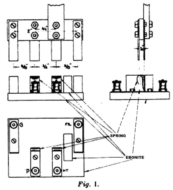
A plug on which the coupling can be mounted is shown in Fig. 1. This plug has a much lower self-capacity and is much easier to make than a valve plug. A piece of ebonite is fixed on the socket to prevent short circuits between HT and filament.
The next improvement overcomes the following disadvantages:-
(a) Any leakage to earth has to pass through the crystal to get back to the valves.
(b) Any A.C. picked up by the circuit can not easily get to earth.
(c) The LT and HT have to be carefully insulated from earth.
All these defects are avoided by connecting the first grid, not to the aerial, but. to a secondary coil coupled to the aerial coil. The crystal-blocking condenser is then disconnected from earth and connected to the free end of the secondary. The -ve filament may be earthed.
If the secondary is loosely coupled it must be tuned, but. if it is tightly coupled it is tuned by virtue of its close coupling and should not have a variable condenser.
A step up can be obtained by winding 50 to 75 percent more turns on the secondary than on the primary. This will considerably increase the signal strength. If the step up is too high, it will be very difficult to prevent oscillation when the plate circuits are tuned.
If the directions of the windings of primary and secondary are in opposition, the reaction condenser can be connected between the first plate and the primary.
To diminish radiation when receiving CW the aerial may be connected to a tuned Coil which is loosely coupled to the tuned HF transformer instead of being connected directly to it as in Figs. 2, 3, and 4.
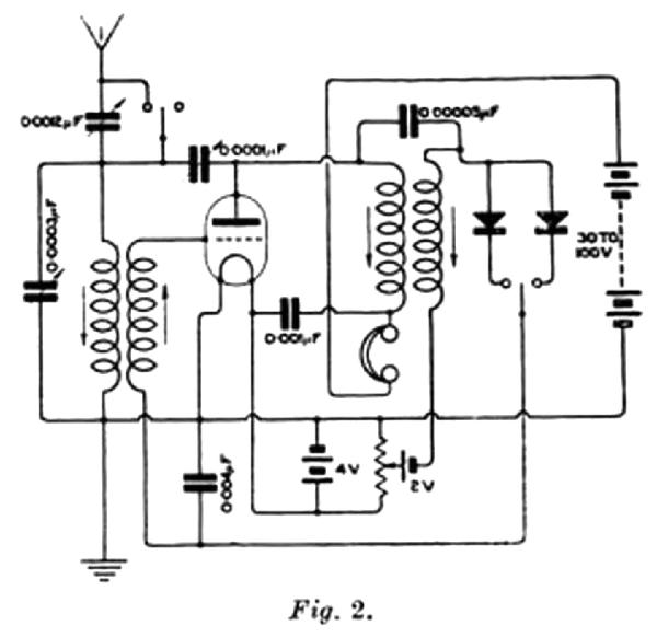 Fig. 2 shows a one-valve dual amplification circuit.
The signal is received on the aerial and tuned in the usual way.
The secondary reverses and steps up the HF voltages to the first grid. In the valve, the HF is amplified and again reversed. A small portion back to the aerial through the reaction condenser and the remainder is passed by the aperiodic HF coupling to the crystal. The HF is rectified by the crystal and applied to the blocking condenser.
Signals would be audible if telephones were connected across this blocking condenser. This condenser is, however, between grid and filament, and therefore the valve produces amplified currents in the telephones in the plate circuit.
 Fig. 3 shows a two-valve circuit. which is the same as Fig. 2, but with the addition of one valve connected by the aperiodic coupling for the HF and by an iron core transformer for the LF.
 In Fig, 4 a two-valve circuit is shown which uses tuned HF transformers for inter-valve coupling. This circuit is more efficient but more difficult to control.
It is sometimes advantageous when using a tuned HF transformer between the valve and crystal to connect it so the voltage is stepped down to the crystal because crystal resistance is usually lower than the valve.
The transformers which I shall describe can be used if connections to the socket can be changed. The tuning condenser is preferably left on the low resistance winding. In Fig. 4 the tuning condenser is shown on this winding, to which the crystal is also connected.
If these circuits buzz instead of oscillating, the trouble can generally be cured by reversing the crystal and adjusting the HT and grid voltages.
An instrument, containing a coupling similar to those described, for converting an LF magnifier into a dual amplifier is now on the market.
It is well known that when the capacity of the parallel condenser in the aerial circuit increases, the voltage efficiency decreases. It is, therefore, not desirable to increase this condenser beyond about 0.0003 µF. The capacity of the average aerial is about 0.0003 µF with the variable condenser at a minimum and about 0.0006 µF with the variable condenser at a maximum.
The maximum wavelength of any coil is consequently about 1.414 (= √2) times its minimum wavelength.
If we try to work out a series of coils so that the wavelength of each coil is 1.414 times the wavelength of the coil below, we get a series of 15 values to include wavelengths from 150 to 27,200 metres.
This would not allow any overlap, and to get overlap, I use coils whose wavelengths have the following values:-
190, 250, 350, 450, 600,800, 1,000, 1,400, 1,900, 2,500, 3,500 metres etc.
When one of these transformers is used in the aerial, the next higher can be used as HF inter-valve transformer if it is tuned by a 0.0003 µF variable condenser, and the next lower can be used as valve to crystal transformer with a 0.0012 µF variable condenser. This makes duplicate or triplicate transformers unnecessary.
When it is not intended to use HF-tuned couplings, such a large number of HF transformers is unnecessary if a series condenser, with which the wavelength of any coil can be reduced, is used.
Only the following coils are then required 190, 350, 600, 1,000, 1,900, 3.500 metres, etc.
It should be noted that as the tuned transformer is used as A.T.I., an ordinary HF transformer wound with very thin copper wire or even resistance wire is quite useless.
My transformers have basket coils as primaries, and as a rough guide, I give particulars of them in Table 1. Lattice and other coils will no doubt, be just as good.
 As the secondaries carry hardly any current, they may be wound with very fine wire such as 42 S.S.C.
It should be wound in narrow slots in the cardboard spider, so that it is as nearly as possible to a single layer winding, which should then be boiled in wax.
It often happens that in manufacture a secondary develops a short circuit. This can be tested as follows:- Tune in a CW station whose wavelength is of the same order as the wavelength for which the secondary is intended. Then hold the secondary near the aerial coil and retune.
If the wavelength has increased, it is due to the self-capacity of the coil under test which is then OK. But if the wavelength has decreased and the tuning has become flat, the coil is faulty.
The wavelength is decreased by the faulty coil on account of the fact that when the magnetic flux tends to thread the coil, eddy currents are set up which repel this flux, with the result that only a small fraction of the initial flux really threads the coil under test.
This has the same effect as reducing the area of the air circuit through which the flux flows, and thus the apparent inductance of the aerial tuning coil is reduced.
As the HF transformers are tuned, a little extra capacity does not matter much, and they can be fitted to R plugs. If it is intended to interchange them with an aperiodic coupling, they should either be fitted with the low capacity plug previously described, or an adaptor should be made so that the R valve plug can be fitted to the low capacity socket.
 It may seem rather strange to use a crystal detector in these days of valves, but when it is remembered that with one valve used for dual amplification signals can be amplified 40 to 200 times, it will be seen that the valve is best employed as an amplifier.
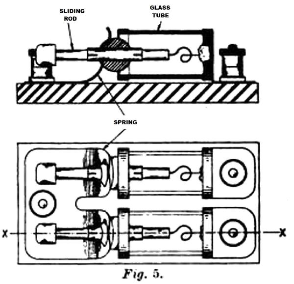
If two crystal detectors are used with a switch so that they can be set, by comparison, no difficulty should be experienced with them, provided they are quite rigid and fitted with good crystals such as treated galena, etc.
Fig. 5 shows a type of detector which is very stable. All necessary weight on the moving parts should be avoided.
These circuits can be used for spark, CW, and telephony, but are particularly good for telephony.
In conclusion, I would like to thank PCGG for his regular transmissions, which have enabled me to make the experiments necessary to develop and perfect these circuits.
To thank the Author because you find the post helpful or well done.