triplett: 3433; FM-AM Signal Generator
? triplett: 3433; FM-AM Signal Generator
I could have made my questions much simpler. I apologize. Here are two questions that will help me diagnose my problem:
If you place one Ohm meter lead on ground and another of the lo rf output, what resistances do you get for each of the multiplier switch settings?
X1 = ?Ω
X10 = ?Ω
X100 = ?Ω
X1M = ?Ω
X10M = ?Ω
HI = ?Ω
If you place one Ohm meter lead on ground and another of the HI rf output, what resistances do you get for each of the multiplier switch settings?
X1 = ?Ω
X10 = ?Ω
X100 = ?Ω
X1M = ?Ω
X10M = ?Ω
HI = ?Ω
Thank you.
To thank the Author because you find the post helpful or well done.
Attenuators
Usually a Pi or Tee Attenuator is used to maintain the amplifier load and the output impedance very stable.
Thus most attenators on Signal generators are for a particular "load" such as 50, 75, (coaxial) or 220, 300, 450 Ohm etc on balanced or older generators. Often x 10,000 is no attenuation and then x1,000 is 20dB attenuation. etc. Sometimes alternate switch positions are used to give better isolation. With a high impedance or wrong impedance (i.e. 50 instead of 450) the switch settings give the wrong levels.
With an Ohm meter you should see a similar resistance on all switch settings and this is the expected load impedance.
Here is my "vintage" Taylor
Modern instruments are either 50 Ohms or 75 Ohms, very much more accurately.
To thank the Author because you find the post helpful or well done.
Signal Generator Attenuators and Multipliers
Thank you very much for your most informative reply. I now understand the function of the multiplier. Consequently, I see that the multiswitch assembly that I rebuilt is indeed wired correctly. The only mistake was that the wires going to the HI RF and LO RF output jacks were reversed. I connected them incorrectly when placing the assembly back into the signal generator. I have corrected that mistake.
Please note the multiswitch assembly schematic below is marked in the blue rectangle. The output jacks circled in red are the two wires that I needed to swap.
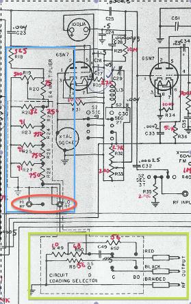
Now, I get an output signal on the HI RF output jack when connecting my PicoScope 3502B. There is no signal on the scope when I connect its probe directly to the LO RF output jack. This is likely because I am missing the "CIRCUIT LOADING SELECTOR" shown in the green rectangle. This must have been part of the signal generator's external circuitry (i.e. a probe). Therefore, I connected the oscilloscope probe to the LO RF output jack through a .047uf capacitor just to test my theory. The result was that the oscilloscope did indeed display the signal!
I now declare this signal generator as functioning. I will continue to test its other features, but already I see that it is very accurate.
I thank you again for such an informative response, and I hope this article helps other owners of the Triplett 3433.
Attachments:- Multiplier Circuit (241 KB)
To thank the Author because you find the post helpful or well done.