unknown: LW/MW SG4 kit: Restoration
unknown: LW/MW SG4 kit: Restoration
Initial Impressions before delivery
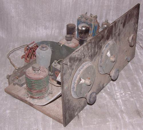
I doubt it's 1920s, though a 1920s style of panel, such panels are common on Kit radio 1931 to 1933. The RF input is likely a SG215 style and the audio out looks to be a 4 pin base Pentode as it has a top cap. The driver can be read as a PM2. The other valve can't be read but is similar appearance (no top cap).
The original ebay photos of my unknown TRF (kit?)


The blue item far left is a transformer. Aerial & Earth are two nearest connections.
The two tuning dials are similar to those on 1928 Mullard kits. The third variable capacitor is likely "reaction"? There is a third large transformer, possibly for a low impedance moving coil speaker as a reed type doesn't need a transformer. That also suggests 1932 /1933, earlier would be reed not moving coil usually.
April 1931 "Radio for the Million" has Pentode PM22 as an option instead of Triode for output on the "Conversion 4" and a SG PM12 for both RF stages. The driver is PM2DX. It's not really similar. That issue still promotes "reed" speakers.
For now we can only guess. But it's more like a "Magazine Kit" than a Mullard or Lissen I think and valves (tubes) and Loudspeaker arrangement too "late" for 1920s.
Probably I spent too much (€31.44 and about €19 shipping) for a really poor (wreck) 1930s kit TRF, but it will give some fun restoring it.
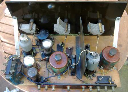
The reality after unpacking and a quick clean
I did take a lot of photos before even I cleaned it and also after simple brush and wipe but before any restoration.
Just a quick wipe, honest, no restoration!


Valves/Tubes in order
Tungsram S210: A SG for tuned RF stage. First large coil, and a large choke for anode load near phone connections.
Mullard HL210: Triode, Tuned Detector and Regeneration (capacitive adjustment). Anode also connects to 1st interstage transformer. which feeds 3rd socket.
Third socket has pin 1 to large blue transformer. It has an Osram VS24K, not a pentode. This is a SG valve and there is no top cap wire. It's obviously the wrong valve.
Last socket is a Mullard PM2, its grid is fed from the big blue transformer and its anode connects to a terminal marked "Phones"
So I made a mistake, what I thought was a Pentode and output transformer was a SG (incorrectly fitted) with inter valve transformer and the other "transformer" is an RF choke for SG (V1) anode supply.
What is it?
It's a late 1920s kit, 1 x SG and 3 x triodes, a common type of TRF with Regeneration. One valve is incorrect. A few wires are missing, but obvious where they should be. Though some companies and magazines publishing this kind of kit up to 1934. A mix of brands suggests a "home brew" rather than complete set of parts (two brands of mica caps, two brands of transformers).
Coils
The coils do have push-pull wave switches but they are siezed. It was easy to remove the switch on one coil, but extremely difficult to free the switch shaft. One switch is now working.
Capacitors.
The two large paper capacitors are so leaky it shows on DMM Ohms range. The base is sealed with wax and card. It's easy to leave it intact internally but with wires snipped and fit a modern capacitor inside too. The others must be Mica, they are fine.
Slow motion Drives
These do work, but a white plastic disc is crumpled up. It's blank!

Drive comes apart relatively easily.
There is a thick rubbery pad between the fixed scale and the panel.
What is the white disc and associated window for? The rotating metal disc has a pointer to the outer log scale. The spring and washer load the knob on the edge of the metal disc for the geared drive.
Next is to "reverse" engineer what is connected. Either it was never finished or someone started to change it. The coil connections don't seem quite right! All the grid bias connections seem to be missing except the grid leak resistor on "V2" HL210
To thank the Author because you find the post helpful or well done.