Wrong pin connections.
Wrong pin connections.

Hello.
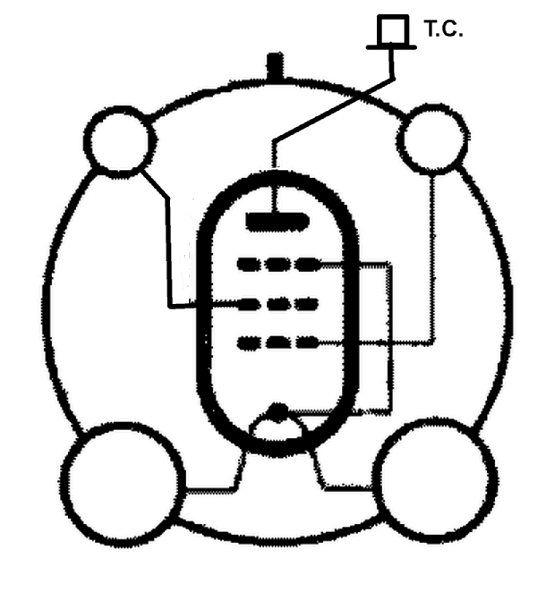
I have noticed that with this valve the pin connection diagram shown is incorrect. Pin 2 is the screen grid and the top cap is the anode.
Regards, Stuart Irwin
To thank the Author because you find the post helpful or well done.
Wrong pin connections.

Hi Stuart,
is this the correct pin assignment of the PM12A_UX?
Does the tube have a bajonet guide pin as shown in the picture?
Is the filament center tap connected to the suppressor grid, as shown in the picture?
If yes, I will replace the presently shown pin assignment picture by this one.
Best regards, Harald
To thank the Author because you find the post helpful or well done.
Wrong pin connections.

Hello together
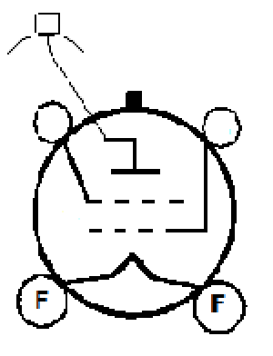
I just uploaded the corrected base diagram;
Kind regards
P.S.
Unsere Beiträge haben sich überschnitten, Harald....
To thank the Author because you find the post helpful or well done.
Wrong pin connections.
Hi all,
Wolfgang's pin assignment picture has now been activated on the PM12A_UX page.
Regards, Harald
To thank the Author because you find the post helpful or well done.
Wrong pin connections.
Hello Harald.
In answer to your questions: That diagram is correct except that there is no suppressor grid. The valve, from an example I have, does have a bayonette pin.
Regards, Stuart
To thank the Author because you find the post helpful or well done.