- Country
- Netherlands
- Manufacturer / Brand
- Airvoice Radio, N. V., Amsterdam
- Year
- 1925
- Category
- Broadcast Receiver - or past WW2 Tuner
- Radiomuseum.org ID
- 196093

Click on the schematic thumbnail to request the schematic as a free document.
- Number of Tubes
- 4
- Main principle
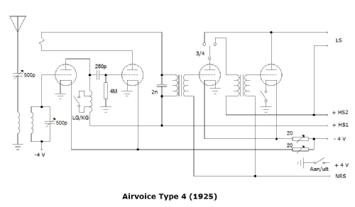
- TRF (Tuned-Radio-Frequency but use of regeneration unknown)
- Tuned circuits
- 2 AM circuit(s)
- Wave bands
- Broadcast (MW) and Long Wave.
- Power type and voltage
- Storage and/or dry batteries / 4 & 45 & 90 Volt
- Loudspeaker
- - This model requires external speaker(s).
- Material
- Wooden case, TUBES VISIBLE.
- from Radiomuseum.org
- Model: Type 4 - Airvoice Radio, N. V.,
- Shape
- Tablemodel, slant panel.
- Dimensions (WHD)
- 340 x 325 x 315 mm / 13.4 x 12.8 x 12.4 inch
- Notes
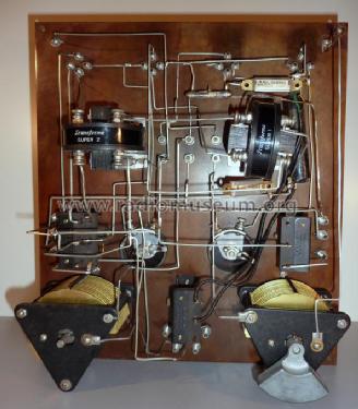
- Ebonite sloping control panel and oak cabinet. Classic lectern shaped model. The control panel was originally made of shining flamed black and brown ebonite. Exposure to sunlight gave the front plate an even brown colour. The highly symmetrical control panel is divided into four rows. In the first row, obscured by the four valves, binding posts for antenna and earth, situated on the upper left and right. In the second row we can see three coil holders. In the third row holds two rheostats. Left of the rheostats a switch that can be used to operate the radio on 3 or 4 valves; the on/off switch is situated on the right of the rheostats. The sockets on the left are for grid bias and filament voltage and the sockets on the left are for the plate voltages. Below the two switches, we see the knobs for primary and secondary tuning, the wave length switch and sockets for headphones and/or loudspeaker. It is a secondary receiver with inductive coupling. A remarkable detail in this circuit is the fact that reaction takes place over two stages, a custom dating back to the time of bright emitters. Because of that, the right coil behaves in a different way: because of the extra phase shift, the point of maximum reaction lays further away from the central coil. The original valve set is not known. Looking at the circuit, both LF tubes must have been the same. The Airvoice Type 7 resembles the Airvoice Type 4 receiver, but that radio has internal coils.
- Source of data
- - - Data from my own collection
- Author
- Model page created by John Koster. See "Data change" for further contributors.
- Other Models
-
Here you find 4 models, 4 with images and 1 with schematics for wireless sets etc. In French: TSF for Télégraphie sans fil.
All listed radios etc. from Airvoice Radio, N. V., Amsterdam