Aircraft Receiver AR8 Type C7733
Amalgamated Wireless (Australasia) Ltd. (AWA); Sydney
- Land
- Australien
- Hersteller / Marke
- Amalgamated Wireless (Australasia) Ltd. (AWA); Sydney
- Jahr
- 1941 ?
- Kategorie
- Militär-Empfänger
- Radiomuseum.org ID
- 342093
eBay item number:266006503239
eBay item number:266006503239
eBay item number:266006503239
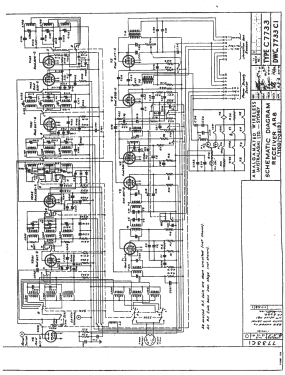
Klicken Sie auf den Schaltplanausschnitt, um diesen kostenlos als Dokument anzufordern.
- Anzahl Röhren
- 11
- Hauptprinzip
- Super mit HF-Vorstufe; ZF/IF 755 kHz
- Wellenbereiche
- Wellen in den Bemerkungen.
- Betriebsart / Volt
- Externes Speisegerät / Netzgerät / Hauptgerät
- Lautsprecher
- - Für Kopfhörer oder NF-Verstärker
- Material
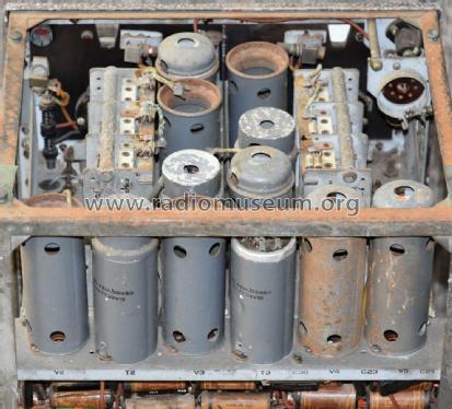
- Metallausführung
- von Radiomuseum.org
- Modell: Aircraft Receiver AR8 Type C7733 - Amalgamated Wireless
- Form
- Chassis - Einbaugerät
- Bemerkung
-
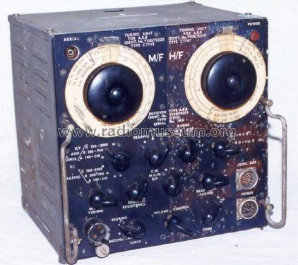
The AR8 receiver is a communications receiver made by AWA during World War 2 for use in aircraft. They were used in locally made aircraft like the Wirraway and imported aircraft like the Hudson.
The AR8 is part of a set that consists of the AR8 receiver, the AT5 transmitter, and an Aerial Coupling Unit. All units are in the shape of a cube and can sit on top of each other. These are connected to a Junction Box and a power supply.
There are 2 power supplies for this radio set. A dynamotor set for 12- or 28-volt DC use, and a mains-powered unit for 240-volt use.The receiver is a unique design as it has 2 RF front ends, and a common IF and Audio section, like the English R1116 receiver.
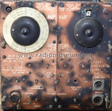
The RF sections are an LF unit and an HF unit and have independent controls, making it easy to switch between 2 stations. There is a red pilot lamp on the top right-hand front panel, to indicate the receiver is on, and a dial light behind each scale, which is turned on for the appropriate RF section, indicating which section is in use.
The valve heaters and pilot lamps are arranged in a series/parallel fashion to enable either 12-volt or 24-volt operation. It has a sensitivity of better than 3 microvolts below 9.5 MHz and better than 10 microvolts above 9.5 MHz. The frequency coverage is 140-740 kHz and 0.765-20 kHz.There is a 6X5GT power rectifier valve which is connected across the antenna input to protect the receiver if the transmitter is accidentally connected and turned on.
LF Section (LH Side)
- Band A: 136-340 kHz
- Band B: 300-740 kHz
- Band C: 765-2050 kHz.
HF Section (RH Side)
- Band D: 2-4.5 MHz
- Band E: 4.2-9.7 MHz
- Band F: 9-20.7 MHz
With the Permission of Ray Poularas and Ray Robinson from Tube Radio Australia.
- Nettogewicht
- 31 lb (31 lb 0 oz) / 14.074 kg
- Literaturnachweis
- - - Manufacturers Literature (A General Purpose Communication Receiver for Military Aircraft, Rudd J.B. and Bushby T.R.W., AWA tec)
- Autor
- Modellseite von Gary Cowans angelegt. Siehe bei "Änderungsvorschlag" für weitere Mitarbeit.
- Weitere Modelle
-
Hier finden Sie 1433 Modelle, davon 877 mit Bildern und 464 mit Schaltbildern.
Alle gelisteten Radios usw. von Amalgamated Wireless (Australasia) Ltd. (AWA); Sydney