Radiola Eighty Ch= C65 Table
Amalgamated Wireless (Australasia) Ltd. (AWA); Sydney
- Paese
- Australia
- Produttore / Marca
- Amalgamated Wireless (Australasia) Ltd. (AWA); Sydney
- Anno
- 1930

- Categoria
- Radio (o sintonizzatore del dopoguerra WW2)
- Radiomuseum.org ID
- 164001
Clicca sulla miniatura dello schema per richiederlo come documento gratuito.
- Numero di tubi
- 6
- Valvole
- 222 222 222 L410_Marconi_UX L410_Marconi_UX P410_UX
- Principio generale
- A circuiti accordati (TRF o amplif. diretta in generale); 2 Stadi BF; A valvole con griglia schermo (solo se 1926-1935)
- Gamme d'onda
- Solo onde medie (OM).
- Tensioni di funzionamento
- Batterie (di accumulatori e/o a secco)
- Altoparlante
- - Questo apparecchio richiede altoparlante/i esterno/i.
- Materiali
- Mobile in legno
- Radiomuseum.org
- Modello: Radiola Eighty Ch= C65 [Table] - Amalgamated Wireless
- Forma
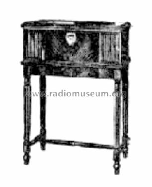
- Soprammobile a cassapanca o cassetta, solitamente con coperchio (NON a leggio)
- Annotazioni
-
Price in November: 48/15/-.
Pedestal for Table Models £ 3/3/- extra.
- Prezzo nel primo anno
- 47.00 Aus£
- Bibliografia
- -- Original prospect or advert (The Sydney Morning Herald, 1930/11/27)
- Letteratura / Schemi (1)
- Wireless Weekly (Australia) (March 20, 1931, Page 19)
- Autore
- Modello inviato da Stuart Irwin. Utilizzare "Proponi modifica" per inviare ulteriori dati.
- Altri modelli
-
In questo link sono elencati 1435 modelli, di cui 879 con immagini e 464 con schemi.
Elenco delle radio e altri apparecchi della Amalgamated Wireless (Australasia) Ltd. (AWA); Sydney
Discussioni nel forum su questo modello: Amalgamated Wireless: Radiola Eighty Ch= C65
Argomenti: 1 | Articoli: 1
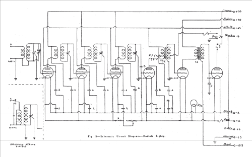
A.W.A. RADIOLA EIGHTY
Details for the Service Mechanic
For our first circuit we have selected one of the popular Radiolas, the model Eighty, a six-valve battery set, which has achieved great popularity in the country districts. Later we will publish other circuits of the Radiola series, although these are not of great value, owing to the extensive service organisation maintained by Amalgamated Wireless. Every receiver sold carries a 12-months’ guarantee, which provides that the set will receive attention only at the hands of a competent engineer, who has been previously instructed in the matter of servicing this particular brand of set. So, it will be seen that there is little need for the Radiola circuits to be published until the receiver in question has been on the market for at least twelve months. Even after this period buyers will find it in their interest to take the receiver to an Authorised Radiola Dealer, who will already have the circuit diagram and servicing hints on hand. For the benefit of those readers who possess Radiolas and are not in a position to take their set to a dealer for attention we publish the following notes, which may be helpful in times of trouble: —
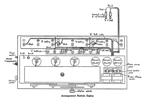
It is advisable not to insert the valves before connecting the batteries when making the first installation. Also, when making battery replacements remove all the valves from their sockets before proceeding to make connections. When making connections, do not permit any battery connector to come in contact with the terminals of other battery connectors, with other battery terminals, or with the metal framework of the set. Such connections cause rapid wastage of the battery power.
Before inserting valves, check the battery connections to see that they are correct, and make sure that the battery switch is in the “Off” position upward. Insert the valves in the positions shown in Fig, I. Do not try to force the large pins on the valve base into the small holes in the socket.
Generally, it will be found that best results will be obtained by using a single wire aerial from 25 to 100 feet long. The “lead-in” and ground connections should be short and direct.
Erect the aerial as high as possible, isolated from other objects, at right angles to electric light or power mains, and special care should be taken to see that it does not cross either above or below such power mains. Support the aerial and “lead-in” by good quality glass or porcelain insulators; arrange the “lead-in” so that it will clear the building by at least a foot and insulate where it is brought in through the window frame or wall. If it is not practicable to install an outdoor aerial, satisfactory results may be obtained by using an indoor aerial. Hang about 20 to 50 feet of insulated wire, about the equivalent of 18-gauge bell wire, around the room preferably high up along the hall or above the ceiling.
An efficient earth connection is essential. Water pipes make good earths; gas pipes should be avoided. If a water pipe is being used for the earth, connect the earth wire to the pipe with an approved pipe clamp, making sure to thoroughly clean the Pipe before fixing the clamp. In the case of a water pipe not being available, drive a pipe or metal rod several feet into the ground.
Wireless Weekly, March 20, 1931, Page 19.
Gary Cowans, 09.Sep.21


