Audio C & R tester
Amroh NV (Radio Bulletin monthly), Muiden
- Paese
- Olanda
- Produttore / Marca
- Amroh NV (Radio Bulletin monthly), Muiden
- Anno
- 1965
- Categoria
- Strumento da laboratorio
- Radiomuseum.org ID
- 231559

Clicca sulla miniatura dello schema per richiederlo come documento gratuito.
- Numero di transistor
- 3
- Gamme d'onda
- - senza
- Tensioni di funzionamento
- Batterie a secco / 9 Volt
- Altoparlante
- AP magnetodinamico (magnete permanente e bobina mobile) / Ø 8.5 cm = 3.3 inch
- Potenza d'uscita
- 0.2 W (qualità ignota)
- Materiali
- Mobile di metallo
- Radiomuseum.org
- Modello: Audio C & R tester - Amroh NV Radio Bulletin
- Forma
- Diverse forme (descritte nelle note).
- Dimensioni (LxAxP)
- 250 x 64 x 125 mm / 9.8 x 2.5 x 4.9 inch
- Annotazioni
-
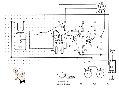
This tester is built in a box from aluminium Uniframe parts: 6x UF 003, 2x UF 004 and 2x UF 005.
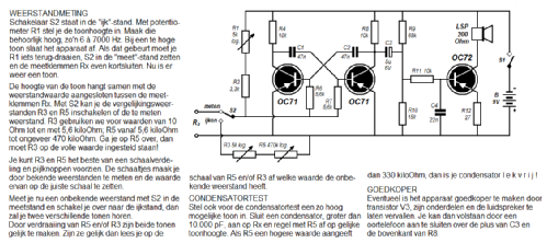
The circuit is based on "measuring" and "verifying" AF frequencies. When they are the same while measuring an unknown resistor, its value can be read on the scales of resistors R3/R5.
When testing a capacitor of 10.000 pF or more, a measured resistance value higher than 330 kOhm means that the capacitor can be regarded as leak-free. Low voltage electrolytic capacitors can be regarded as leak-free when the measured value is higher than 100 kOhm.
- Bibliografia
- Radio Blan edition 31, 1 september 1965
- Autore
- Modello inviato da Rob Majoor. Utilizzare "Proponi modifica" per inviare ulteriori dati.
- Altri modelli
-
In questo link sono elencati 240 modelli, di cui 208 con immagini e 231 con schemi.
Elenco delle radio e altri apparecchi della Amroh NV (Radio Bulletin monthly), Muiden