40F 25 Hz mains
Atwater Kent Mfg. Co.; Philadelphia, USA
- Country
- United States of America (USA)
- Manufacturer / Brand
- Atwater Kent Mfg. Co.; Philadelphia, USA
- Year
- 1928
- Category
- Broadcast Receiver - or past WW2 Tuner
- Radiomuseum.org ID
- 98842
From a Canadian Kijiji advertisement.
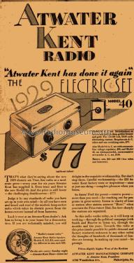
Atwater Kent Print Ad
From a Canadian Kijiji advertisement.
From a Canadian Kijiji advertisement.
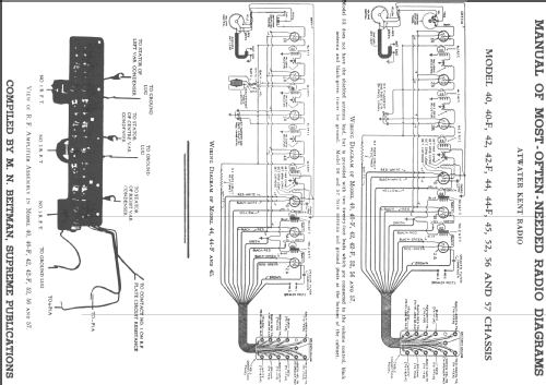
Click on the schematic thumbnail to request the schematic as a free document.
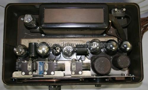
- Number of Tubes
- 7
- Main principle
- TRF without regeneration
- Tuned circuits
- 3 AM circuit(s)
- Wave bands
- Broadcast only (MW).
- Power type and voltage
- Alternating Current supply (AC) / 115 Volt
- Loudspeaker
- - This model requires external speaker(s).
- Material
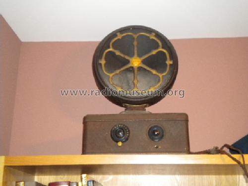
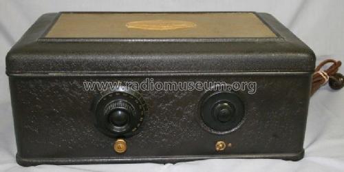
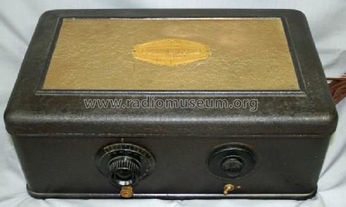
- Metal case
- from Radiomuseum.org
- Model: 40F [25 Hz mains] - Atwater Kent Mfg. Co.;
- Shape
- Tablemodel, Box - most often with Lid (NOT slant panel).
- Notes
- Version "F" for 25 Hz mains supply.
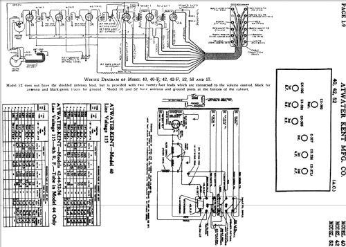
- Circuit diagram reference
- Rider's Perpetual, Volume 1 = 1931/1934 (for 1919-1931)
- Literature/Schematics (1)
- -- Schematic
- Author
- Model page created by Arpad Roth † 27.3.17. See "Data change" for further contributors.
- Other Models
-
Here you find 507 models, 331 with images and 332 with schematics for wireless sets etc. In French: TSF for Télégraphie sans fil.
All listed radios etc. from Atwater Kent Mfg. Co.; Philadelphia, USA
Forum contributions about this model: Atwater Kent Mfg. Co: 40F
Threads: 1 | Posts: 2
How can I tell the difference between The Atwater Kent Model 40f and the 9800 Model 40? Thanks in advance for any info given. Regards, Les
Les Lawrence, 16.Jun.12