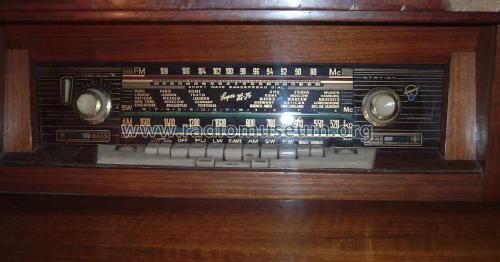
New Yorker 40403
Blaupunkt (Ideal), Berlin, später Hildesheim
- Country
- Germany
- Manufacturer / Brand
- Blaupunkt (Ideal), Berlin, später Hildesheim
- Year
- 1960 ?
- Category
- Broadcast Receiver - or past WW2 Tuner
- Radiomuseum.org ID
- 160657
-
- alternative name: Ideal-Radiotelephon- und App-fabr. || Ideal-Werke AG; Berlin (ab 1934)
- Brand: Rotstern
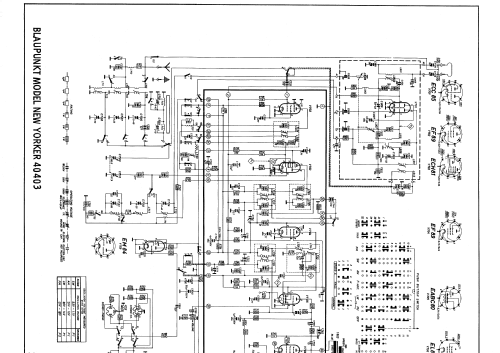
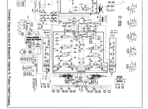
Click on the schematic thumbnail to request the schematic as a free document.
- Number of Tubes
- 0
- Number of Transistors
- Semiconductors
- B250C250
- Main principle
- Superhet with RF-stage; ZF/IF 460/10700 kHz; Export model
- Tuned circuits
- 7 AM circuit(s) 12 FM circuit(s)
- Wave bands
- Broadcast, Long Wave, Short Wave plus FM or UHF.
- Details
- Changer (Record changer)
- Power type and voltage
- Alternating Current supply (AC) / 110; 127; 155; 220 Volt
- Loudspeaker
- 7 or more Loudspeakers
- Power out
- 50 W (unknown quality)
- Material
- Wooden case
- from Radiomuseum.org
- Model: New Yorker 40403 - Blaupunkt Ideal, Berlin,
- Shape
- Console with Push Buttons.
- Dimensions (WHD)
- 1470 x 900 x 400 mm / 57.9 x 35.4 x 15.7 inch
- Notes
-
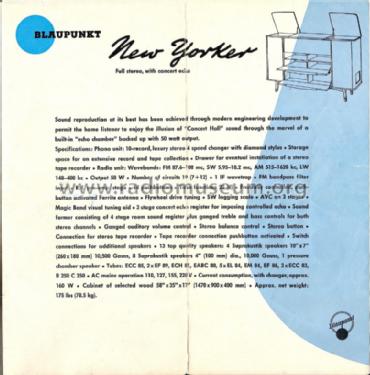
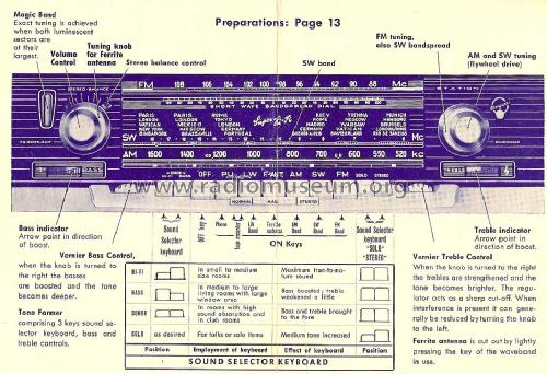
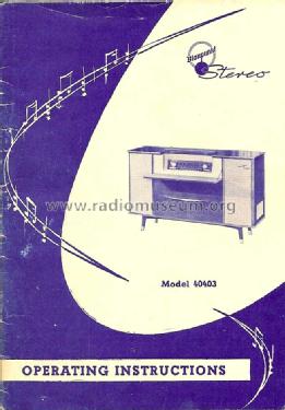
Blaupunkt New Yorker 40403 is an export model for the USA with an FM range up to 108 MHz.
It is equipped with 13 speakers: 4x Suprakustik 10" x 7", 8x Suprakustik 4", and 1 pressure chamber speaker for the built-in acoustic delay function.
See the domestic version New York Vollstereo 40400 for service instructions.
Note: "T" behind capacitor values means thousand pf = nf.
- Net weight (2.2 lb = 1 kg)
- 78.5 kg / 172 lb 14.5 oz (172.907 lb)
- Mentioned in
- -- Original prospect or advert
- Author
- Model page created by Heribert Jung. See "Data change" for further contributors.
- Other Models
-
Here you find 3591 models, 3280 with images and 2332 with schematics for wireless sets etc. In French: TSF for Télégraphie sans fil.
All listed radios etc. from Blaupunkt (Ideal), Berlin, später Hildesheim
Collections
The model New Yorker is part of the collections of the following members.
Forum contributions about this model: Blaupunkt Ideal,: New Yorker 40403
Threads: 1 | Posts: 8
This is my first post to this forum, so please have patience with me. I need advice to proceed further with the restoration of this type 40400 Blaupunkt New York console stereo radio and record changer. As received, it was dead and was to be disposed of as trash. Since I am a novice radio restorer, I was unsure I could repair it. It has taken me six months of study and poking at this radio to bring it to its current state-UKW band sounds excellent (I cannot take credit for this as it has been problem free from the start); MW band sounds excellent but has some buzz (normal?) between stations; KW also sounds good but I believe that it needs to have the MW band switched on previously in order to receive stations strongly. LW is characterized by a loud buzz and no stations (I can duplicate this loud buzz on MW and KW bands by placing my Voltmeter probe on Pin 2(grid) of the RF amplifier tube (EF89). Until 2 weeks ago, the radio received only UKW, the upper portion of the MW band and no KW. Using a frequency counter, I determined that the radio would stop oscillating on the low frequency end of the MW band; no oscillation at all occurred on the KW band. I found C712, a 36 Pf tubular capacitor in the oscillator circuit to be defective. When replaced, the MW band was restored and the KW also began to recive stations-however it appears that if the KW is switched on first, it does not receive as many staions as when MW is played first and then KW is then switched on afterwards.
The oscillator voltage, as measured with Heathkit VTVM and radio frequency probe is between 4.5 and 7 volts on KW; 6 to 8 volts on MW and 7 to 10 volts on LW. ECH 81 shows the following:
Pin 1: 91 volts; (schematic shows 92 volts for MW, no value for KW).
Pin 6 (mixer plate): 231 volts on MW and KW; (schematic shows 242 volts for MW, no value for KW).
Pin 8 (oscillator plate): 65 volts on KW and 108 on MW; (schematic shows 108 on MW, no value for KW).
EF89 (the RF amplifier, V702) shows the folowing:
Pin 7 (plate): 196 volts on KW and 235 volts on MW. (Schematic shows 225 volts on MW)
Pin 8 (screen): 60 volts on KW and 70 volts on MW (schematic shows 22 Volts on MW, no value for KW).
EF 89 (IF amplifier) shows 228 volts for MW on Pin 7 (plate) and 74 volts on pin 8 (screen), both are in accord with schematic.
EABC80 shows 65 volts on Pin 9 (plate) on both MW and KW. Schematic shows 82 volts, so detector plate voltage is low.
EL 84 (V706) shows normal voltages (202 on plate and 215 on screen).
Most electrolytic capacitors in this radio (in both the high frequency portion and the amplifier section) have been replaced by me-approximately 4 small electrolytics still remain to be replaced. New main filter electrolytics were installed and the selenium rectifier replaced with 4 diodes and 4 snubber capacitors as reccomended in this forum. B plus voltage is now steady at 291 volts. Can anyone provide further advice at this time?
Regards,
Robert Sottile
Robert Sottile, 02.Dec.06
