FET DIP Oscillator G3WPO Mk1 (Ambit)
Cirkit dist.Ltd. (Ambit); Broxbourne
- Produttore / Marca
- Cirkit dist.Ltd. (Ambit); Broxbourne
- Anno
- 1981–1987
- Categoria
- Strumento da laboratorio
- Radiomuseum.org ID
- 211591


Clicca sulla miniatura dello schema per richiederlo come documento gratuito.
- Numero di transistor
- 5
- Semiconduttori
- Principio generale
- A circuiti accordati (amplif. diretta) con rivelazione a diodo
- N. di circuiti accordati
- 1 Circuiti Mod. Amp. (AM)
- Gamme d'onda
- Gamme d'onda nelle note.
- Tensioni di funzionamento
- Batterie a secco / 9 Volt
- Altoparlante
- AP elettrostatico (necessita di alta tensione continua di polarizzazione) / Ø 1 inch = 2.5 cm
- Potenza d'uscita
- 0.01 W (qualità ignota)
- Materiali
- Mobile di metallo
- Radiomuseum.org
- Modello: FET DIP Oscillator G3WPO Mk1 - Cirkit dist.Ltd. Ambit;
- Forma
- Apparecchio portatile > 20 cm (senza la necessità di una rete)
- Dimensioni (LxAxP)
- 58 x 92 x 125 mm / 2.3 x 3.6 x 4.9 inch
- Annotazioni
- DIP oscillator and Wave meter
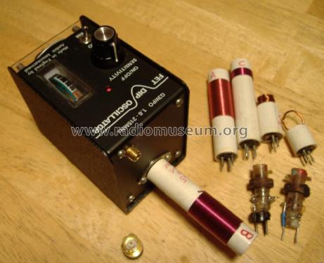
5 Wavebands from 1.8MHz to 215MHz
A: 1.6 ... 4.2
B: 3.5 ... 10.0
C: 9 ... 26
D: 25 ... 90
E: 80 ... 210
Progressivly poorer "dip" at lower bands in Oscillator "GDO" mode
Sensitivity control varies drive from peak rectifier diodes to meter rather than oscillator level
Audible tone volume controlled by detected level (piezo-ceramic beeper)
You can add your own coils. A common modificaton is an FET buffer (2N3819 or similar) to drive a frequency counter.
Labelled "Made in England by Ambit International", the MkII in 1987 is "Cirkit" branded and adds a resistor on the plug in coils to set Oscillator level, so coils are not exchangeable. See Articles for operation and use.
- Peso netto
- 0.320 kg / 0 lb 11.3 oz (0.705 lb)
- Autore
- Modello inviato da Michael Watterson. Utilizzare "Proponi modifica" per inviare ulteriori dati.
- Altri modelli
-
In questo link sono elencati 2 modelli, di cui 2 con immagini e 2 con schemi.
Elenco delle radio e altri apparecchi della Cirkit dist.Ltd. (Ambit); Broxbourne
Collezioni
Il modello FET DIP Oscillator fa parte delle collezioni dei seguenti membri.
Discussioni nel forum su questo modello: Cirkit dist.Ltd.: FET DIP Oscillator G3WPO Mk1
Argomenti: 1 | Articoli: 2
If you search on "Dip Meter" on RMorg you may find 60 pages of results. My first meter was something like this Leader (link) in about 1981. Joe Sousa suggested I write something as the "Dip meter use" is almost like a lost art today. I left the Leader Transistor Dip Meter behind when I moved in 1983.
Originally called a Grid Dip Meter or GDO (Grid Dip Oscillator) when they used a valve (tube), the name has stuck and often bipolar or Transistor or FET Dip Meters are also called "GDO".
The principle is simply to have an oscillator where the tuning coil is external and easily influenced by coupling to another tuned circuit. A diode detector feeds a meter so the oscillator level is visible. If an external tuned circuit is at the same frequency then some of the oscillator power will couple to it and the meter needle will dip as you move the tuning capcitor past the resonance. The meter can thus be used to tune aerial "traps", IF filters and loop aerials. If the oscillator is too powerful or stable then the dip will be too small. This is why the main tuned circuit is usually on the grid, base or gate of the amplifier.
Band switching is just manually using a different plug in coil.
Today with cheap 0.01% or better frequency meters that work 100kHz to 2GHz a good option is an FET buffer on the oscillator to drive a counter for accurate frequency display. This output can also be used as a "cheap" RF signal gernerator.
Most meters have a mode where the oscillation is disabled. This is traditionally called a "wavemeter". It's nothing more than a single tuned "crystal radio" or TRF with a meter replacing the headphones!
One problem is that without a band dependent oscillator gain control the oscillator can be too strong on the lower bands and thus little or no "dip". The G2WPO mk1 suffers badly from this which is largely mitigated on the mk2 by using dual gate FETs and a gain set resistor on each plug in coil.
Michael Watterson, 31.Jan.12