Magnum 20-watt Amplifier
Cooper-Smith (Brand), H.L. Smith & Co. Ltd.; London
- País
- Gran Bretaña (GB)
- Fabricante / Marca
- Cooper-Smith (Brand), H.L. Smith & Co. Ltd.; London
- Año
- 1961
- Categoría
- Amplificador de audio o mezclador
- Radiomuseum.org ID
- 339337
Haga clic en la miniatura esquemática para solicitarlo como documento gratuito.
- Numero de valvulas
- 5
- Principio principal
- Amplificador de Audio
- Gama de ondas
- - no hay
- Tensión de funcionamiento
- Red: Corriente alterna (CA, Inglés = AC) / 200,220 & 240 Volt
- Altavoz
- - Este modelo usa altavoz exterior (1 o más).
- Material
- Metálico con lámparas a la vista.
- de Radiomuseum.org
- Modelo: Magnum 20-watt Amplifier - Cooper-Smith Brand, H.L. Smith
- Forma
- Chasis (tambien de autoradio)
- Ancho, altura, profundidad
- 14 x 8.25 x 7.75 inch / 356 x 210 x 197 mm
- Anotaciones
-
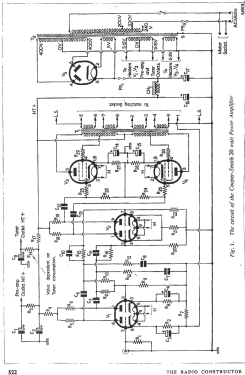
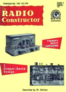
The Cooper-Smith 20-watt power amplifier provides a true high-fidelity output at high power. It is an instrument that is ideal for high-grade sound reinforcement and public address systems, and it can also fulfill applications in the domestic field. In the latter case, the amplifier would normally be operated below its rated output, the fact that it has a considerable degree of undistorted power in reserve ensuring that transients and the like are reproduced truthfully without approaching overload at any time.
Features;
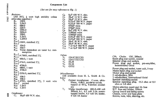
The amplifier is designed to operate in conjunction with the Cooper-Smith Mk. II Control Unit, although other pre-amplifiers could be used instead if they meet input requirements. Power supply sockets are available both for the pre-amplifier and for the radio or tuner unit. There is also an outlet that may be used for supplying mains voltage to a gram motor or to any similar ancillary equipment.
On-off switching for the power amplifier is achieved at the Control Unit, and the pre-amplifier socket carries the necessary wiring for this facility.
A special feature of the amplifier is given by the output transformer. This component is of heavy construction and employs C-cores instead of normal laminations to keep leakage inductances to a minimum. The transformer is coupled to the output valves in an ultra-linear circuit. Output impedances at 3.8, 8.5, and 15.2 ohms are available these being selected by fitting individual plugs into a special 9-way matching socket. The plugs are identified by the output impedance they provide and they are wired internally such that appropriate combinations of the output transformer secondary windings are presented to the two loudspeaker terminals.
The plugs also carry components that enter the negative feedback loop, these components ensuring that feedback at the correct level is achieved whatever output impedance is selected.
Special attention has been paid to the design of the amplifier to the prevention of hum. A center-tapped 6.3 volt secondary on the mains transformer supplies the heater of the first two valves in the amplifier circuit and is available for use by the pre-amplifier and radio tuner unit as well.
Main HT smoothing is carried out with paper, and not electrolytic, condensers. Fuses are provided both in the mains input and in the HT supply circuit.Specifications:
- Power Output: 20 watts nominal, 30 watts max.
- Frequency Response: 20 - 30,000 Hz ±0.5 dB at full output
- Distortion: 0.1 % at full output
- Output Impedances: 3.8 Ω, 8.5 Ω and 15.2 Ω.
- Feedback: 26 dB
- Input Sensitivity: 650 mV for 29.3 watts output
- Noise Level: -80 dB referred to 29.3 watts
- Spare Power: 250V at 45mA, 6.3V at 2A.
- Peso neto
- 26 lb (26 lb 0 oz) / 11.804 kg
- Mencionado en
- -- Original prospect or advert (The Radio Constructor, February, and March 1961.)
- Documentación / Esquemas (1)
- -- Original prospect or advert (The Radio Constructor, Feb 1961 Page 522)
- Autor
- Modelo creado por Gary Cowans. Ver en "Modificar Ficha" los participantes posteriores.
- Otros modelos
-
Donde encontrará 6 modelos, 4 con imágenes y 5 con esquemas.
Ir al listado general de Cooper-Smith (Brand), H.L. Smith & Co. Ltd.; London